Toyota Camry (XV70): Installation
INSTALLATION
PROCEDURE
1. INSTALL CAMSHAFT TIMING GEAR BOLT
(a) Make sure that the No. 1 cylinder is at TDC/compression.
HINT:
Check that the cutout of the camshaft timing gear assembly is at the top and align the timing mark (cutout) of the crankshaft pulley with the timing mark on the timing chain cover assembly.
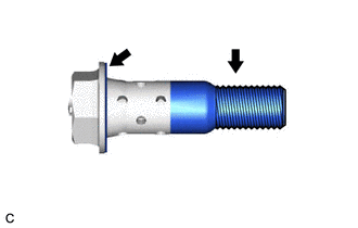
| (b) Apply engine oil to the areas of the camshaft timing gear bolt shown in the illustration. |
|
(c) While holding the crankshaft pulley, temporarily install the camshaft timing gear bolt.
Torque:
10 N·m {102 kgf·cm, 7 ft·lbf}
NOTICE:
- If the camshaft timing gear bolt has been struck or dropped, replace it.
- If there is any abnormal resistance when temporarily installing the camshaft timing gear bolt, loosen it and make sure that the No. 1 cylinder is at TDC/compression, and then temporarily install the camshaft timing gear bolt again.
HINT:
Make sure that the flange part of the camshaft timing gear bolt contacts the entire circumference of the camshaft timing gear assembly.
(d) While holding the crankshaft pulley, tighten the camshaft timing gear bolt.
Torque:
95 N·m {969 kgf·cm, 70 ft·lbf}
NOTICE:
Do not use an impact wrench.
2. INSTALL CAMSHAFT TIMING OIL CONTROL SOLENOID ASSEMBLY (for Exhaust Side of Bank 1)
Click here .gif)
3. INSPECT FOR ENGINE OIL LEAK
Click here
4. INSTALL V-BANK COVER SUB-ASSEMBLY
Click here
5. INSTALL FRONT FENDER APRON SEAL RH
Click here
6. INSTALL FRONT WHEEL RH
Click here
READ NEXT:
 Components
COMPONENTS ILLUSTRATION
*1 FRONT FENDER APRON SEAL RH
*2 V-BANK COVER SUB-ASSEMBLY
N*m (kgf*cm, ft.*lbf): Specified torque
- - ILLUSTRATION
*1
Removal
REMOVAL PROCEDURE 1. REMOVE FRONT WHEEL RH
Click here 2. REMOVE FRONT FENDER APRON SEAL RH
Click here
3. REMOVE V-BANK COVER SUB-ASSEMBLY Click here
4. REMOVE CAMSHAFT TI
SEE MORE:
Data List / Active Test
DATA LIST / ACTIVE TEST DATA LIST NOTICE:
In the table below, the values listed under "Normal Condition" are reference values. Do not depend solely on these reference values when deciding whether a part is faulty or not.
HINT: Using the Techstream to read the Data List allows the values or state
Satellite Radio Broadcast cannot be Selected or After Selecting Broadcast, Broadcast cannot be Added into Memory
CAUTION / NOTICE / HINT NOTICE: Some satellite radio broadcasts require payment. A contract must be made between a satellite radio company and the user. If the contract expires, it will not be possible to listen to the broadcast. PROCEDURE
1.
CHECK SATELLITE RADIO (a) Check radio condi
