Toyota Camry (XV70): Installation
INSTALLATION
PROCEDURE
1. INSTALL VVT SENSOR (for Exhaust Side of Bank 2)
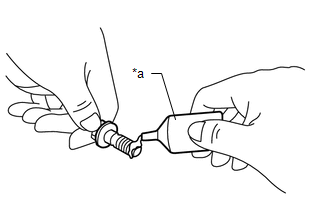
(a) Apply a light coat of engine oil to the O-ring of the VVT sensor.
NOTICE:
If reusing the VVT sensor, be sure to inspect the O-ring.
(b) Clean the bolt and bolt hole.
| (c) Apply adhesive to 2 or 3 threads at the end of the bolt. Adhesive: Toyota Genuine Adhesive 1324, Three Bond 1324 or equivalent |
|
(d) Install the VVT sensor to the cylinder head cover sub-assembly LH with the bolt.
Torque:
10 N·m {102 kgf·cm, 7 ft·lbf}
NOTICE:
- If the VVT sensor has been struck or dropped, replace it.
- Make sure that the O-ring is not cracked or moved out of place when installing the VVT sensor.
(e) Connect the VVT sensor connector.
2. INSTALL VVT SENSOR (for Intake Side of Bank 2)
(a) Apply a light coat of engine oil to the O-ring of the VVT sensor.
NOTICE:
If reusing the VVT sensor, be sure to inspect the O-ring.
(b) Clean the bolt and bolt hole.
| (c) Apply adhesive to 2 or 3 threads at the end of the bolt. Adhesive: Toyota Genuine Adhesive 1324, Three Bond 1324 or equivalent |
|
(d) Install the VVT sensor to the cylinder head cover sub-assembly LH with the bolt.
Torque:
10 N·m {102 kgf·cm, 7 ft·lbf}
NOTICE:
- If the VVT sensor has been struck or dropped, replace it.
- Make sure that the O-ring is not cracked or moved out of place when installing the VVT sensor.
(e) Connect the VVT sensor connector.
3. INSTALL VVT SENSOR (for Exhaust Side of Bank 1)
(a) Apply a light coat of engine oil to the O-ring of the VVT sensor.
NOTICE:
If reusing the VVT sensor, be sure to inspect the O-ring.
(b) Clean the bolt and bolt hole.
| (c) Apply adhesive to 2 or 3 threads at the end of the bolt. Adhesive: Toyota Genuine Adhesive 1324, Three Bond 1324 or equivalent |
|
(d) Install the VVT sensor to the cylinder head cover sub-assembly with the bolt.
Torque:
10 N·m {102 kgf·cm, 7 ft·lbf}
NOTICE:
- If the VVT sensor has been struck or dropped, replace it.
- Make sure that the O-ring is not cracked or moved out of place when installing the VVT sensor.
(e) Connect the VVT sensor connector.
4. INSTALL VVT SENSOR (for Intake Side of Bank 1)
(a) Apply a light coat of engine oil to the O-ring of the VVT sensor.
NOTICE:
If reusing the VVT sensor, be sure to inspect the O-ring.
(b) Clean the bolt and bolt hole.
| (c) Apply adhesive to 2 or 3 threads at the end of the bolt. Adhesive: Toyota Genuine Adhesive 1324, Three Bond 1324 or equivalent |
|
(d) Install the VVT sensor to the cylinder head cover sub-assembly with the bolt.
Torque:
10 N·m {102 kgf·cm, 7 ft·lbf}
NOTICE:
- If the VVT sensor has been struck or dropped, replace it.
- Make sure that the O-ring is not cracked or moved out of place when installing the VVT sensor.
(e) Connect the VVT sensor connector.
5. INSTALL INTAKE AIR SURGE TANK ASSEMBLY
Click here .gif)
6. INSPECT FOR ENGINE OIL LEAK
Click here
READ NEXT:
 Crankshaft Position Sensor
ComponentsCOMPONENTS ILLUSTRATION
*1 CRANKSHAFT POSITION SENSOR
*2 CRANKSHAFT POSITION SENSOR PROTECTOR
N*m (kgf*cm, ft.*lbf): Specified torque
- - Remova
Components
COMPONENTS ILLUSTRATION
*1 AIR CLEANER ASSEMBLY WITH AIR CLEANER HOSE
*2 COOL AIR INTAKE DUCT SEAL
*3 ECM
*4 INLET AIR CLEANER ASSEMBLY
*5 NO. 1 ECM BRA
SEE MORE:
Components
COMPONENTS ILLUSTRATION
*1 FRONT DISC BRAKE ANTI-SQUEAL SHIM KIT
*2 FRONT DISC BRAKE CYLINDER ASSEMBLY
*3 FRONT DISC BRAKE PAD
*4 FRONT FLEXIBLE HOSE
*5 FRONT NO. 1 DISC BRAKE ANTI-SQUEAL SHIM
*6 FRONT NO. 2 DISC BRAKE ANTI-SQUEAL SHIM
Maintenance
requirements
To ensure safe and economical driving, day-to-day care and regular
maintenance are essential. It is the owner's responsibility to
perform regular checks. Toyota recommends the following maintenance:
General maintenance
General maintenance should be performed on a daily basis. This can
be done b
