Toyota Camry (XV70): Components
COMPONENTS
ILLUSTRATION
|
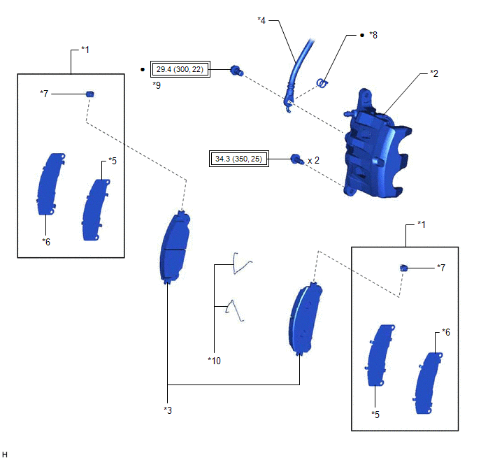
*1 | FRONT DISC BRAKE ANTI-SQUEAL SHIM KIT |
*2 | FRONT DISC BRAKE CYLINDER ASSEMBLY |
|
*3 | FRONT DISC BRAKE PAD |
*4 | FRONT FLEXIBLE HOSE |
|
*5 | FRONT NO. 1 DISC BRAKE ANTI-SQUEAL SHIM |
*6 | FRONT NO. 2 DISC BRAKE ANTI-SQUEAL SHIM |
|
*7 | FRONT DISC BRAKE PAD WEAR INDICATOR PLATE |
*8 | GASKET |
|
*9 | UNION BOLT |
*10 | ANTI-SQUEAL SPRING |
.png) |
Tightening torque for "Major areas involving basic vehicle performance such as moving/turning/stopping": N*m (kgf*cm, ft.*lbf) |
● | Non-reusable part |
ILLUSTRATION
|
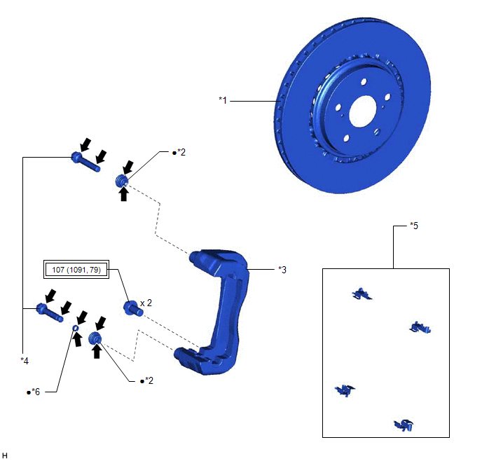
*1 | FRONT DISC |
*2 | FRONT DISC BRAKE BUSHING DUST BOOT |
|
*3 | FRONT DISC BRAKE CYLINDER MOUNTING |
*4 | FRONT DISC BRAKE CYLINDER SLIDE PIN |
|
*5 | FRONT DISC BRAKE PAD SUPPORT PLATE |
*6 | FRONT DISC BRAKE CYLINDER SLIDE BUSHING |
|
|
Tightening torque for "Major areas involving basic vehicle performance such as moving/turning/stopping": N*m (kgf*cm, ft.*lbf) |
● | Non-reusable part |
.png) |
Lithium soap base glycol grease |
- | - |
ILLUSTRATION
|
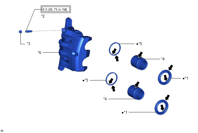
*1 | CYLINDER BOOT |
*2 | FRONT DISC BRAKE BLEEDER PLUG |
|
*3 | FRONT DISC BRAKE BLEEDER PLUG CAP |
*4 | FRONT DISC BRAKE PISTON |
|
*5 | PISTON SEAL |
*6 | FRONT DISC BRAKE CYLINDER |
|
|
Tightening torque for "Major areas involving basic vehicle performance such as moving/turning/stopping": N*m (kgf*cm, ft.*lbf) |
● | Non-reusable part |
|
|
Lithium soap base glycol grease |
- | - |
READ NEXT:
 Removal
REMOVAL CAUTION / NOTICE / HINT
NOTICE:
Immediately after installing the front disc brake pads, the braking performance may be reduced. Always perform a road test in a safe place while paying at
Disassembly
DISASSEMBLY CAUTION / NOTICE / HINT
HINT: Perform the removal and installation of the front disc brake piston, cylinder boot and piston seal one side at a time. PROCEDURE
1. REMOVE FRONT DISC BRAK
Inspection
INSPECTION PROCEDURE 1. INSPECT BRAKE CYLINDER AND PISTON
(a) Check the front disc brake cylinder bore and front disc brake piston for rust and scoring. If necessary, replace the front disc brake cy
SEE MORE:
Registration
REGISTRATION PROCEDURE 1. REGISTER TRANSMITTER CODE
HINT:
The vehicle garage door opener records transmitter codes for systems such as garage doors, gates, entry gates, door locks, home lighting systems, security systems or other transmitter code based systems.
The garage door opener is b
Pressure Control Solenoid "L" Circuit Short to Battery (P08BA12)
DESCRIPTION Changing gears is performed by the ECM turning the solenoid (SL1, SL2, SL3, SL4, SL5 and SL6) valves on and off.
If an open or short occurs in any of the solenoid valve circuits, the ECM controls the remaining normal solenoid valves to allow the vehicle to be driven. If all of the sole
