Toyota Camry (XV70): Removal
REMOVAL
CAUTION / NOTICE / HINT
NOTICE:
- Immediately after installing the front disc brake pads, the braking performance may be reduced. Always perform a road test in a safe place while paying attention to the surroundings.
- After replacing the front disc brake pads, always perform a road test to check the braking performance and check for vibrations.
HINT:
- Use the same procedure for the RH side and LH side.
- The following procedure is for the LH side.
PROCEDURE
1. REMOVE FRONT WHEEL
Click here
.gif)
2. DRAIN BRAKE FLUID
NOTICE:
If brake fluid leaks onto any painted surface, immediately wash it off.
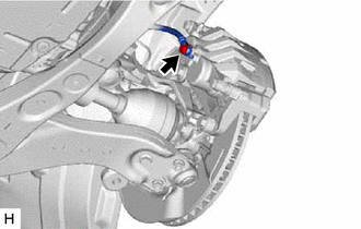
3. DISCONNECT FRONT FLEXIBLE HOSE
| (a) Remove the union bolt and gasket, and disconnect the front flexible hose from the front disc brake cylinder assembly. |
|
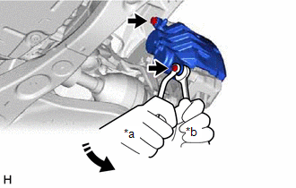
4. REMOVE FRONT DISC BRAKE CYLINDER ASSEMBLY
| (a) Hold the 2 front disc brake cylinder slide pins and remove the 2 bolts and front disc brake cylinder assembly. |
|
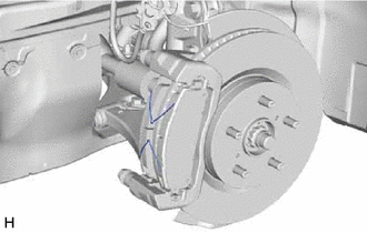
5. REMOVE FRONT DISC BRAKE PAD
| (a) Remove the 2 anti-squeal springs. |
|
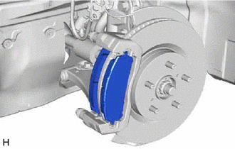
| (b) Remove the 2 front disc brake pads from the front disc brake cylinder mounting. |
|
6. REMOVE FRONT DISC BRAKE ANTI-SQUEAL SHIM KIT
Click here
.gif)
7. REMOVE FRONT DISC BRAKE PAD SUPPORT PLATE
| (a) Remove the 4 front disc brake pad support plates from the front disc brake cylinder mounting. NOTICE: Each front disc brake pad support plate has a different shape. Be sure to put an identification mark on each front disc brake pad support plate so that it can be reinstalled to its original position. |
|
8. REMOVE FRONT DISC BRAKE CYLINDER SLIDE PIN
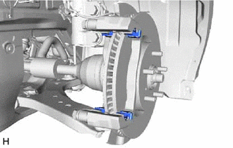
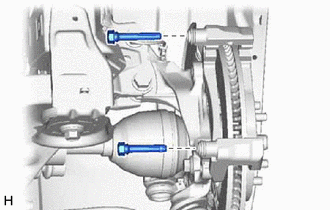
| (a) Remove the 2 front disc brake cylinder slide pins from the front disc brake cylinder mounting. |
|
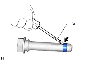
| (b) Using a screwdriver with its tip wrapped with protective tape, remove the front disc brake cylinder slide bushing from the front disc brake cylinder slide pin (lower side). NOTICE: Do not damage the front disc brake cylinder slide pin. |
|
9. REMOVE FRONT DISC BRAKE BUSHING DUST BOOT
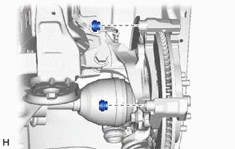
| (a) Remove the 2 front disc brake bushing dust boots from the front disc brake cylinder mounting. |
|
10. REMOVE FRONT DISC BRAKE CYLINDER MOUNTING
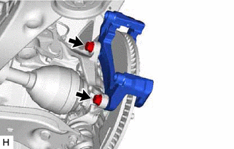
| (a) Remove the 2 bolts and front disc brake cylinder mounting from the steering knuckle. |
|
11. REMOVE FRONT DISC
|
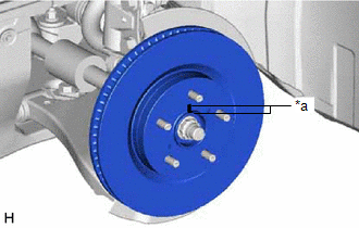
(a) Put matchmarks on the front disc and the front axle hub sub-assembly. |
|
(b) Remove the front disc.

