Toyota Camry (XV70): Installation
INSTALLATION
PROCEDURE
1. INSTALL KNOCK CONTROL SENSOR
HINT:
Perform "Inspection After Repair" after replacing a knock control sensor.
Click here .gif)
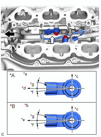
(a) Temporarily install the 2 knock control sensors to the cylinder block sub-assembly with the 2 bolts so that the knock control sensor installation position is as shown in the illustration.
|
*A | for Bank 1 |
|
*B | for Bank 2 |
|
*a | View A |
|
*b | View B |
|
*c | Top |
|
*d | Engine Front |
|
*e | Engine Rear |
|
*f | 5° |
|
*g | 10° |
.png) |
Engine Front |
.png) |
View A |
 |
View B |
NOTICE:
- If a knock control sensor has been struck or dropped, replace it.
- Make sure that the knock control sensor is installed in the correct position.
| (b) Tighten the bolt (A). Torque: 20 N·m {204 kgf·cm, 15 ft·lbf} |
|
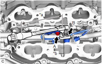
(c) Using a 10 mm union nut wrench, tighten the bolt (B).
Torque:
Specified tightening torque :
20 N·m {204 kgf·cm, 15 ft·lbf}
HINT:
- Calculate the torque wrench reading when changing the fulcrum length of the torque wrench.
Click here
- When using a 10 mm union nut wrench (fulcrum length of 22 mm (0.866 in.)) + torque wrench (fulcrum length of 162 mm (6.38 in.)):
17.6 N*m (179 kgf*cm, 13 ft.*lbf)
(d) Connect the 2 knock control sensor connectors.
2. INSTALL FUEL DELIVERY PIPE
Click here
3. PERFORM INITIALIZATION
(a) Perform "Inspection After Repair" after replacing a knock control sensor.
Click here
READ NEXT:
 Components
COMPONENTS ILLUSTRATION
*1 MASS AIR FLOW METER SUB-ASSEMBLY
- -
On-vehicle Inspection
ON-VEHICLE INSPECTION PROCEDURE
1. INSPECT MASS AIR FLOW METER SUB-ASSEMBLY HINT: Perform "Inspection After Repair" after replacing the mass air flow meter sub-assembly.
Click here
(a) Rea
SEE MORE:
HD Radio Tuner Malfunction (B1551,B158D,B15A0,B15B0,B15B3,B15B7,B15BA,B15F9)
DESCRIPTION These DTCs are stored when a malfunction occurs in the radio and display receiver assembly.
DTC No. Detection Item
DTC Detection Condition Trouble Area
B1551 HD Radio Tuner Malfunction
When any of the following conditions is met:
"HD Radio" tuner d
Components
COMPONENTS ILLUSTRATION
*1 BATTERY
*2 NEGATIVE BATTERY TERMINAL
*3 POSITIVE BATTERY TERMINAL
*4 NO. 2 BATTERY CLAMP
*5 BATTERY TERMINAL CAP
- -
Tightening torque for "Major areas involving basic vehicle performance such as moving
