Toyota Camry (XV70): Installation
INSTALLATION
PROCEDURE
1. INSTALL FUEL PIPE PLUG SUB-ASSEMBLY
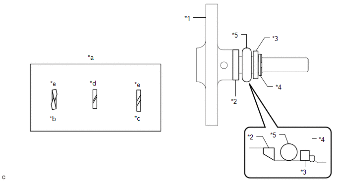
(a) Install a new O-ring, No. 1 fuel injector back-up ring, No. 2 fuel injector back-up ring and No. 3 fuel injector back-up ring to the fuel pipe plug sub-assembly as shown in the illustration.
|
*1 | Fuel Pipe Plug Sub-assembly |
*2 | No. 1 Fuel Injector Back-up Ring |
|
*3 | No. 2 Fuel Injector Back-up Ring |
*4 | No. 3 Fuel Injector Back-up Ring |
|
*5 | O-ring |
- | - |
|
*a | Opening |
*b | Overlapped |
|
*c | Stretched |
*d | Correct |
|
*e | Incorrect |
- | - |
NOTICE:
- Check that there is no foreign matter or damage on the O-ring groove of the fuel pipe plug sub-assembly.
- Check that the No. 1 fuel injector back-up ring and No. 3 fuel injector back-up ring are installed in the correct orientation.
- Make sure that the No. 1 fuel injector back-up ring, No. 2 fuel injector back-up ring, No. 3 fuel injector back-up ring and O-ring are installed in the correct order.
- Check that the opening of the No. 1 fuel injector back-up ring is not overlapped or stretched as shown in the illustration.
- After installing the O-ring, check that it is not contaminated with foreign matter and is not damaged.
(b) w/ Dust Cap:
(1) Install the dust cap sub-assembly to the fuel pipe plug sub-assembly.
| (c) Install a new gasket to the fuel pipe plug sub-assembly as shown in the illustration. |
|

(d) Secure the fuel delivery pipe with sensor assembly LH in a vise between aluminum plates.
NOTICE:
Do not overtighten the vise.
(e) Using a 5 mm hexagon socket wrench, install the fuel pipe plug sub-assembly to the fuel delivery pipe with sensor assembly LH with the 2 bolts.
Torque:
10 N·m {102 kgf·cm, 7 ft·lbf}
(f) Remove the fuel delivery pipe with sensor assembly LH from the vise.
2. INSTALL FUEL PRESSURE SENSOR (FUEL DELIVERY PIPE WITH SENSOR ASSEMBLY LH)
HINT:
Perform "Inspection After Repair" after replacing the fuel pressure sensor (fuel delivery pipe with sensor assembly LH).
Click here .gif)
Click here
NOTICE:
- Do not remove the fuel pressure sensor from the fuel delivery pipe with sensor assembly LH.
- If the fuel pressure sensor is removed, replace the fuel pressure sensor (fuel delivery pipe with sensor assembly LH) with a new one.
3. PERFORM INITIALIZATION
(a) Perform "Inspection After Repair" after replacing the fuel pressure sensor (fuel delivery pipe with sensor assembly LH).
Click here
READ NEXT:
 Inspection
INSPECTION PROCEDURE 1. INSPECT FUEL PRESSURE SENSOR (FUEL DELIVERY PIPE WITH SENSOR ASSEMBLY LH)
NOTICE:
Do not remove the fuel pressure sensor from the fuel delivery pipe with sensor assembly
Installation
INSTALLATION PROCEDURE 1. INSTALL FUEL PIPE PLUG SUB-ASSEMBLY
(a) Install a new O-ring, No. 1 fuel injector back-up ring, No. 2 fuel injector back-up ring and No. 3 fuel injector back-up ring to the
SEE MORE:
Fail-safe Chart
FAIL-SAFE CHART FAIL-SAFE CHART (a) When the skid control ECU (brake actuator assembly) detects a solenoid valve malfunction or abnormal signal from a sensor, the brake actuator assembly cuts power and sends a signal indicating a malfunction of the vehicle stability control system to the ECM.
HINT
Left Front Wheel Speed Sensor Internal Electronic Failure (C050049)
DESCRIPTION When the system is starting up and the skid control ECU (brake actuator assembly) detects a speed sensor circuit malfunction via the speed sensor circuit self-diagnosis function, this DTC is stored.
DTC No. Detection Item
DTC Detection Condition Trouble Area
C05004
