Toyota Camry (XV70): Linear Solenoid Circuit (C1298)
DESCRIPTION
The 4WD ECU assembly receives signals from each sensor to control clutch fluid pressure for limiting the center differential operation, which distributes torque according to the driving conditions.
|
DTC No. | Detection Item |
DTC Detection Condition | Trouble Area |
|---|---|---|---|
|
C1298 | Linear Solenoid Circuit |
When all of the following continue for 1 second or more:
|
|
|
Vehicle Condition | |||
|---|---|---|---|
|
Pattern 1 | Pattern 2 | ||
|
Diagnosis Condition | IG1 voltage is 9.5 V or more, the current requested by the 4WD linear solenoid (transmission coupling assembly) is 0 A. |
○ | - |
|
IG1 voltage is 9.5 V or more, the current requested by the 4WD linear solenoid (transmission coupling assembly) is greater than 0.8 A. |
- | ○ | |
|
Malfunction Status | Short occurs in the 4WD linear solenoid circuit. |
○ | - |
|
Open occurs in the 4WD linear solenoid circuit. |
- | ○ | |
|
Detection Time | 1 second or more |
1 second or more | |
|
Number of Trips | 1 trip |
1 trip | |
HINT:
DTC will be output when conditions for either of the patterns in the table above is met.
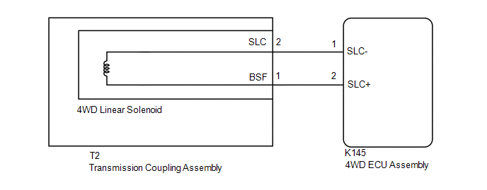
WIRING DIAGRAM

PROCEDURE
| 1. |
CHECK HARNESS AND CONNECTOR (4WD ECU ASSEMBLY - TRANSMISSION COUPLING ASSEMBLY) |
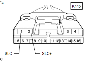
| (a) Disconnect the K145 4WD ECU assembly connector. |
|
(b) Measure the resistance according to the value(s) in the table below.
Standard Resistance:
|
Tester Connection | Condition |
Specified Condition |
|---|---|---|
|
K145-2 (SLC+) - K145-1 (SLC-) |
20 |


