Toyota Camry (XV70): On-vehicle Inspection
ON-VEHICLE INSPECTION
PROCEDURE
1. REMOVE COWL TOP VENTILATOR LOUVER SUB-ASSEMBLY
Click here
.gif)
2. REMOVE FRONT CENTER UPPER SUSPENSION BRACE SUB-ASSEMBLY
Click here .gif)
.gif)
3. OPERATION CHECK
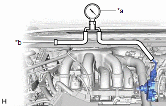
(a) Slide the clip and disconnect the air tube from the vacuum pump assembly.
| (b) Connect the hose of the vacuum gauge to the vacuum pump assembly. |
|
(c) Start the engine and warm it up for more than 2 minutes.
(d) With the engine idling, check the vacuum of the vacuum pump assembly.
Standard Pressure:
More than 86.7 kPa (650 mmHg, 25.6 in.Hg)
HINT:
If the result is not as specified, replace the vacuum pump assembly.
(e) Remove the vacuum gauge from the vacuum pump assembly.
(f) Connect the air tube to the vacuum pump assembly, and slide the clip to secure it.
4. INSTALL FRONT CENTER UPPER SUSPENSION BRACE SUB-ASSEMBLY
Click here
.gif)
.gif)
.gif)
5. INSTALL COWL TOP VENTILATOR LOUVER SUB-ASSEMBLY
Click here .gif)
READ NEXT:
REMOVAL PROCEDURE 1. REMOVE THROTTLE BODY WITH MOTOR ASSEMBLY
Click here 2. REMOVE NO. 2 SURGE TANK STAY
Click here
3. SEPARATE ENGINE WIRE
(a) Remove the 2 bolts and separate the eng
INSTALLATION PROCEDURE 1. INSTALL VACUUM PUMP ASSEMBLY
(a) Clean the vacuum pump assembly installation bolt holes in the camshaft housing sub-assembly and cylinder head sub-assembly.
(b) When usin
SEE MORE:
INSTALLATION PROCEDURE 1. INSTALL STEREO COMPONENT AMPLIFIER ASSEMBLY
2. INSTALL NO. 2 AMPLIFIER BRACKET (a) Install the No. 2 amplifier bracket with the 2 screws.
3. INSTALL NO. 1 AMPLIFIER BRACKET (a) Install the No. 1 amplifier bracket with the 2 screws.
4. INSTALL STEREO COMPONENT AMPLIFIE
DESCRIPTION HINT: Although the DTC titles say oxygen sensor, these DTCs relate to the air fuel ratio sensor.
The air fuel ratio sensor generates voltage* that corresponds to the actual air fuel ratio. This sensor voltage is used to provide the ECM with feedback so that it can control the air fuel
.gif)
.gif)
.gif)
.gif)
.gif)
.gif)
.gif)


