Toyota Camry (XV70): Removal
REMOVAL
PROCEDURE
1. REMOVE THROTTLE BODY WITH MOTOR ASSEMBLY
Click here .gif)
2. REMOVE NO. 2 SURGE TANK STAY
Click here
3. SEPARATE ENGINE WIRE
| (a) Remove the 2 bolts and separate the engine wire. |
|
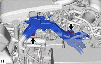
| (b) Remove the bolt and separate the earth wire. |
|
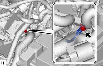
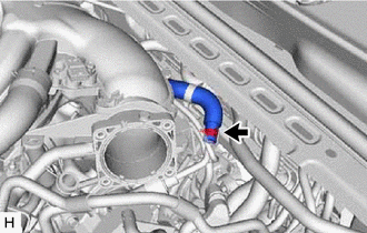
4. DISCONNECT AIR TUBE
|
(a) Slide the clip and disconnect the air tube from the vacuum pump assembly. |
|
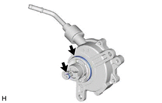
5. REMOVE VACUUM PUMP ASSEMBLY
| (a) Remove the 3 bolts and vacuum pump assembly from the engine assembly. |
|

| (b) Remove the 2 O-rings from the vacuum pump assembly. |
|
READ NEXT:
 Installation
INSTALLATION PROCEDURE 1. INSTALL VACUUM PUMP ASSEMBLY
(a) Clean the vacuum pump assembly installation bolt holes in the camshaft housing sub-assembly and cylinder head sub-assembly.
(b) When usin
Components
COMPONENTS ILLUSTRATION
*1 ENGINE WIRE
*2 NO. 1 VACUUM HOSE CONNECTOR
*3 VACUUM PUMP ASSEMBLY
*4 NO. 1 VACUUM PUMP O-RING
Tightening torque for "Ma
SEE MORE:
Panoramic moon roof
Use the overhead switches to operate the panoramic moon roof
and electronic sunshade.
Opening and closing the electronic sunshade
Opens the electronic sunshade
Slide and hold the switch
backward. The electronic sunshade
will fully open automatically.*
Closes the electronic sunshade
Problem Symptoms Table
PROBLEM SYMPTOMS TABLE
HINT:
Use the table below to help determine the cause of problem symptoms. If multiple suspected areas are listed, the potential causes of the symptoms are listed in order of probability in the "Suspected Area" column of the table. Check each symptom by checking the susp
© 2023-2025 Copyright www.tocamry.com
