Toyota Camry (XV70): Components
COMPONENTS
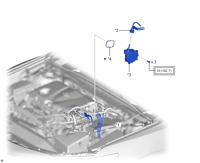
ILLUSTRATION
|
*1 | ENGINE WIRE |
*2 | NO. 1 VACUUM HOSE CONNECTOR |
|
*3 | VACUUM PUMP ASSEMBLY |
*4 | NO. 1 VACUUM PUMP O-RING |
.png) |
Tightening torque for "Major areas involving basic vehicle performance such as moving/turning/stopping": N*m (kgf*cm, ft.*lbf) |
● | Non-reusable part |
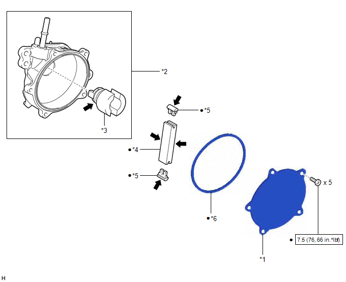
ILLUSTRATION
|
*1 | END COVER |
*2 | VACUUM PUMP HOUSING |
|
*3 | VACUUM PUMP ROTOR |
*4 | VACUUM PUMP VANE |
|
*5 | VACUUM PUMP VANE CAP |
*6 | VACUUM PUMP COVER O-RING |
.png) |
N*m (kgf*cm, ft.*lbf): Specified torque |
● | Non-reusable part |
.png) |
Engine oil | - |
- |
READ NEXT:
 On-vehicle Inspection
ON-VEHICLE INSPECTION PROCEDURE
1. OPERATION CHECK (a) Slide the clip and disconnect the union to check valve hose from the vacuum pump assembly.
(b) Connect the hose of the vacuum gauge to th
Removal
REMOVAL CAUTION / NOTICE / HINT
NOTICE: This procedure includes the removal of small-head bolts. Refer to Small-Head Bolts of Basic Repair Hint to identify the small-head bolts.
Click here
Disassembly
DISASSEMBLY PROCEDURE 1. REMOVE END COVER
(a) To prevent the coupling of the vacuum pump assembly from contacting the workbench, support the vacuum pump assembly with wooden blocks or an equival
SEE MORE:
Removal
REMOVAL CAUTION / NOTICE / HINT
The necessary procedures (adjustment, calibration, initialization or registration) that must be performed after parts are removed and installed, or replaced during park/neutral position switch assembly removal/installation are shown below. Necessary Procedures After
Components
COMPONENTS ILLUSTRATION
*1 REAR ENGINE UNDER COVER LH
*2 FRONT FENDER APRON SEAL LH
*3 NO. 1 ENGINE UNDER COVER
*4 FRONT WHEEL OPENING EXTENSION PAD LH
*5 FRONT WHEEL OPENING EXTENSION PAD RH
- -
N*m (kgf*cm, ft.*lbf): Specified
© 2023-2025 Copyright www.tocamry.com
