Toyota Camry (XV70): On-vehicle Inspection
ON-VEHICLE INSPECTION
PROCEDURE
1. INSPECT THROTTLE BODY WITH MOTOR ASSEMBLY
(a) Before cleaning, or after cleaning the throttle body with motor assembly and installing it to the vehicle, turn the engine switch on (IG) without operating the accelerator pedal sensor assembly.
NOTICE:
If the accelerator pedal sensor assembly has been operated, restart the procedure from the step above.
(b) Connect the Techstream to the DLC3 and check for DTCs. If DTCs are stored, repair them by following the repair procedure flow. If DTCs are not stored, perform the throttle body operation check.
(c) Check throttle body operation.
(1) Enter the following menus:
Powertrain / Engine / Active Test / Control the ETCS Open/Close Slow Speed
(2) During Active Test operation, check the Data List items "Throttle Position Command" and "Throttle Position Sensor No. 1 Voltage".
Powertrain > Engine > Active Test|
Active Test Display |
|---|
|
Control the ETCS Open/Close Slow Speed |
|
Data List Display |
|---|
|
Throttle Position Sensor No.1 Voltage |
|
Throttle Position Command |

|
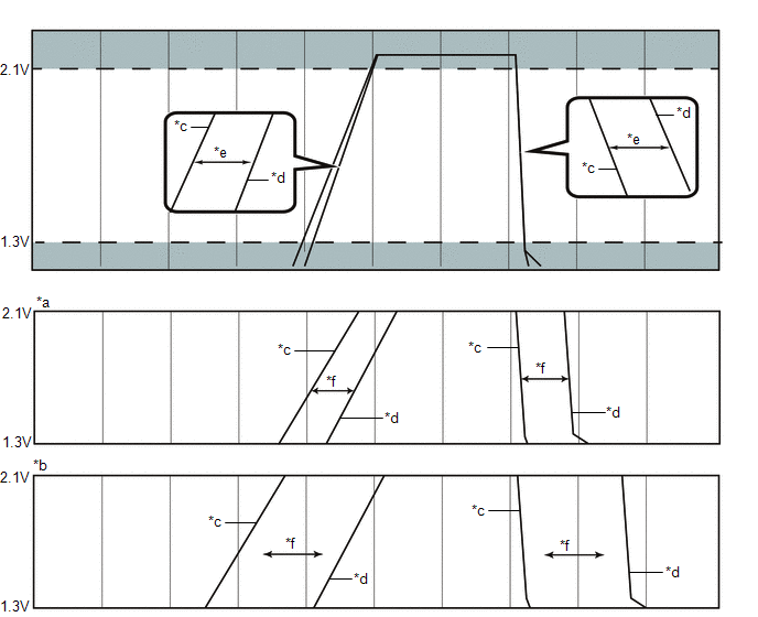
*a | Correct |
*b | Incorrect |
|
*c | Throttle Position Command |
*d | Throttle Position Sensor No.1 Voltage |
|
*e | Specified Condition |
*f | 200 ms |
OK:
| Tester Display |
Condition | Specified Condition |
|---|---|---|
|
Throttle Position Command Throttle Position Sensor No.1 Voltage |
Checked during Active Test operation at a voltage of 1.3 V to 2.1 V. |
Response lag between Throttle Position Command and Throttle Position Sensor No. 1 Voltage is within 200 ms. |
(3) Enter the following menus:
Powertrain / Engine / Active Test / Control the ETCS Open/Close Fast Speed
(4) During Active Test operation, check the Data List items "Throttle Position Command" and "Throttle Position Sensor No. 1 Voltage".
Powertrain > Engine > Active Test|
Active Test Display |
|---|
|
Control the ETCS Open/Close Fast Speed |
|
Data List Display |
|---|
|
Throttle Position Sensor No.1 Voltage |
|
Throttle Position Command |
|
*a | Correct |
*b | Incorrect |
|
*c | Throttle Position Command |
*d | Throttle Position Sensor No.1 Voltage |
|
*e | Specified Condition |
*f | 200 ms |
OK:
| Tester Display |
Condition | Specified Condition |
|---|---|---|
|
Throttle Position Command Throttle Position Sensor No.1 Voltage |
Checked during Active Test operation at a voltage of 1.3 V to 2.1 V. |
Response lag between Throttle Position Command and Throttle Position Sensor No. 1 Voltage is within 200 ms. |
(d) Warm up the engine.
NOTICE:
- The A/C switch and all accessory switches should be off.
- The electric fan should be off.
- After warming up the engine, check that the coolant temperature is 75° C or more.
(e) Check the "Throttle Position Sensor No.1 Voltage %".
(1) Read the Data List while quickly and fully depressing the accelerator pedal and check that the value for "Throttle Position Sensor No.1 Voltage %" is 60% or more.
(f) If there was any abnormality found during the throttle body operation check or "Throttle Position Sensor No.1 Voltage %" check, clean the throttle body, then reassemble it and perform the throttle body operation check again. If the operation returns to normal, the procedure is complete. If operation does not return to normal, replace the throttle body with motor assembly.
(g) Perform "Inspection After Repair" after replacing or cleaning the throttle body with motor assembly.
Click here .gif)
READ NEXT:
 Removal
REMOVAL CAUTION / NOTICE / HINT
The necessary procedures (adjustment, calibration, initialization, or registration) that must be performed after parts are removed and installed, or replaced during t
Inspection
INSPECTION PROCEDURE 1. INSPECT THROTTLE BODY WITH MOTOR ASSEMBLY
(a) Measure the resistance according to the value(s) in the table below.
Standard Resistance:
Tester Connection Con
Installation
INSTALLATION PROCEDURE 1. INSTALL THROTTLE BODY GASKET
(a) Install a new throttle body gasket to the intake air surge tank assembly with the protrusion of the throttle body gasket oriented as sh
SEE MORE:
Components
COMPONENTS ILLUSTRATION
*1 PROPELLER SHAFT HEAT INSULATOR
*2 NO. 1 PROPELLER SHAFT HEAT INSULATOR BRACKET SUB-ASSEMBLY
*3 REAR ENGINE MOUNTING BRACKET SUB-ASSEMBLY
*4 TRANSFER ASSEMBLY
Tightening torque for "Major areas involving basic vehicle per
Left Rear Wheel Speed Sensor Circuit Intermittent (C050C1F)
DESCRIPTION Refer to DTC C050C12 Click here
DTC No. Detection Item
DTC Detection Condition Trouble Area
C050C1F Left Rear Wheel Speed Sensor Circuit Intermittent
The speed sensor signal is excessively noisy.
The calculated change in wheel speed is more t
