Toyota Camry (XV70): Removal
REMOVAL
CAUTION / NOTICE / HINT
The necessary procedures (adjustment, calibration, initialization, or registration) that must be performed after parts are removed and installed, or replaced during throttle body with motor assembly removal/installation are shown below.
Necessary Procedures After Parts Removed/Installed/Replaced|
Replaced Part or Performed Procedure |
Necessary Procedure | Effect/Inoperative Function when Necessary Procedure not Performed |
Link |
|---|---|---|---|
| Inspection after repair |
|
|
PROCEDURE
1. DRAIN ENGINE COOLANT
Click here
.gif)
2. REMOVE AIR CLEANER CAP WITH AIR CLEANER HOSE
| (a) Disconnect the mass air flow meter sub-assembly connector. |
|
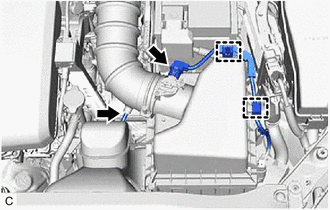
(b) Disengage the 2 wire harness clamps.
(c) Disconnect the vacuum hose from the air cleaner hose.
| (d) Disengage the 2 clamps to disconnect the No. 1 fuel vapor feed hose from the air cleaner hose. |
|
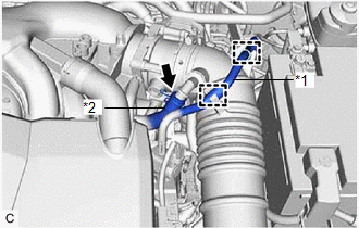
(e) Slide the clip and disconnect the No. 2 ventilation hose from the air cleaner hose.
| (f) Disengage the 2 air cleaner cap clamps. |
|
(g) Disengage the 2 guides to separate the air cleaner cap sub-assembly from the air cleaner case sub-assembly.
| (h) Loosen the hose clamp and remove the air cleaner cap with air cleaner hose from the throttle body with motor assembly. |
|
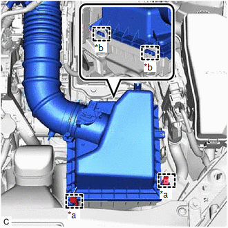
3. REMOVE THROTTLE BODY WITH MOTOR ASSEMBLY
| (a) Slide the 2 clips and disconnect the No. 2 water by-pass hose and No. 3 water by-pass hose from the throttle body with motor assembly. |
|

| (b) Disconnect the throttle body with motor assembly connector. |
|
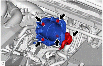
(c) Remove the 4 bolts and throttle body with motor assembly from the intake air surge tank assembly.
NOTICE:
If the throttle body with motor assembly has been struck or dropped, replace it.
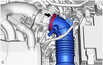
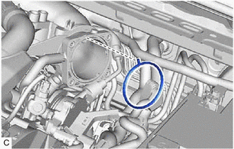
4. REMOVE THROTTLE BODY GASKET
| (a) Remove the throttle body gasket from the intake air surge tank assembly. |
|
READ NEXT:
 Inspection
INSPECTION PROCEDURE 1. INSPECT THROTTLE BODY WITH MOTOR ASSEMBLY
(a) Measure the resistance according to the value(s) in the table below.
Standard Resistance:
Tester Connection Con
Installation
INSTALLATION PROCEDURE 1. INSTALL THROTTLE BODY GASKET
(a) Install a new throttle body gasket to the intake air surge tank assembly with the protrusion of the throttle body gasket oriented as sh
SEE MORE:
Components
COMPONENTS ILLUSTRATION
*1 FRONT WHEEL OPENING EXTENSION PAD LH
*2 FRONT WHEEL OPENING EXTENSION PAD RH
*3 NO. 1 ENGINE UNDER COVER
*4 REAR ENGINE UNDER COVER LH
*5 REAR ENGINE UNDER COVER RH
- -
N*m (kgf*cm, ft.*lbf): Specified
Clearance Warning Buzzer
ComponentsCOMPONENTS ILLUSTRATION
*A for 7 Inch Display
*B for 9 Inch Display
*1 CENTER INSTRUMENT CLUSTER FINISH PANEL ASSEMBLY
*2 CENTER INSTRUMENT CLUSTER FINISH PANEL SUB-ASSEMBLY
*3 LOWER INSTRUMENT PANEL FINISH PANEL ASSEMBLY
*4 NO. 1 CLE
