Toyota Camry (XV70): Components
COMPONENTS
ILLUSTRATION

|
*1 | FRONT WHEEL OPENING EXTENSION PAD LH |
*2 | FRONT WHEEL OPENING EXTENSION PAD RH |
|
*3 | NO. 1 ENGINE UNDER COVER |
*4 | REAR ENGINE UNDER COVER LH |
|
*5 | REAR ENGINE UNDER COVER RH |
- | - |
.png) |
N*m (kgf*cm, ft.*lbf): Specified torque |
- | - |
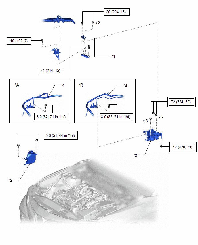
ILLUSTRATION

|
*1 | V-BANK COVER SUB-ASSEMBLY |
- | - |
ILLUSTRATION
|
*A | Type A |
*B | Type B |
|
*1 | NO. 2 ENGINE MOUNTING STAY RH |
*2 | RADIATOR RESERVE TANK ASSEMBLY |
|
*3 | ENGINE MOUNTING INSULATOR SUB-ASSEMBLY RH |
*4 | SUCTION HOSE SUB-ASSEMBLY |
 |
Tightening torque for "Major areas involving basic vehicle performance such as moving/turning/stopping": N*m (kgf*cm, ft.*lbf) |
|
N*m (kgf*cm, ft.*lbf): Specified torque |
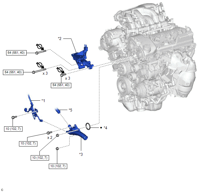
ILLUSTRATION
|
*1 | ENGINE WIRE |
*2 | FRONT NO. 1 ENGINE MOUNTING BRACKET LH |
|
*3 | WATER INLET WITH THERMOSTAT SUB-ASSEMBLY |
*4 | GASKET |
|
*5 | WATER BY-PASS HOSE |
- | - |
|
|
N*m (kgf*cm, ft.*lbf): Specified torque |
● | Non-reusable part |
 |
Do not apply lubricants to the threaded parts |
- | - |
READ NEXT:
 Removal
REMOVAL PROCEDURE 1. REMOVE FRONT WHEEL OPENING EXTENSION PAD LH
Click here
2. REMOVE FRONT WHEEL OPENING EXTENSION PAD RH Click here
3. REMOVE ENGINE UNDER COVER NO.1
Click here
Inspection
INSPECTION PROCEDURE 1. INSPECT WATER INLET WITH THERMOSTAT SUB-ASSEMBLY
(a) Check the valve opening. HINT: The valve opening temperature is inscribed on the water inlet with thermostat sub-assembly
Installation
INSTALLATION PROCEDURE 1. INSTALL WATER INLET WITH THERMOSTAT SUB-ASSEMBLY
(a) Install a new gasket to the water inlet with thermostat sub-assembly.
(b) Install the water inlet with thermostat sub
SEE MORE:
Crankshaft Position - Camshaft Position Correlation Bank 1 Sensor A (P001600,P001800)
DESCRIPTION In the VVT (Variable Valve Timing) system, the appropriate intake valve open and close timing is controlled by the ECM. The ECM performs intake valve control by performing the following: 1) controlling the intake camshaft, cam timing oil control solenoid assembly, camshaft timing gear bo
Reassembly
REASSEMBLY PROCEDURE 1. INSTALL NO. 1 OIL NOZZLE SUB-ASSEMBLY
(a) Using a 5 mm hexagon socket wrench, install the 3 No. 1 oil nozzle sub-assemblies to the cylinder block sub-assembly with the 3 bolts.
Torque: 9.0 N·m {92 kgf·cm, 80 in·lbf}
2. INSTALL PISTON HINT: Perfo
