Toyota Camry (XV70): Removal
REMOVAL
PROCEDURE
1. REMOVE FRONT WHEEL OPENING EXTENSION PAD LH
Click here .gif)
2. REMOVE FRONT WHEEL OPENING EXTENSION PAD RH
Click here
3. REMOVE ENGINE UNDER COVER NO.1
Click here
4. REMOVE ENGINE UNDER COVER REAR LH
Click here
5. REMOVE ENGINE UNDER COVER REAR RH
Click here
6. DRAIN ENGINE COOLANT
Click here
7. REMOVE V-BANK COVER SUB-ASSEMBLY
Click here
8. REMOVE ENGINE MOUNTING STAY NO.2 RH
Click here
9. SEPARATE RADIATOR RESERVE TANK ASSEMBLY
| (a) Disengage the clamp. |
|
(b) Remove the bolt, nut to separate the radiator reserve tank assembly.
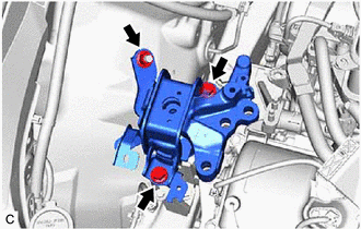
10. REMOVE ENGINE MOUNTING INSULATOR SUB-ASSEMBLY RH
(a) Disengage the 2 clamps.
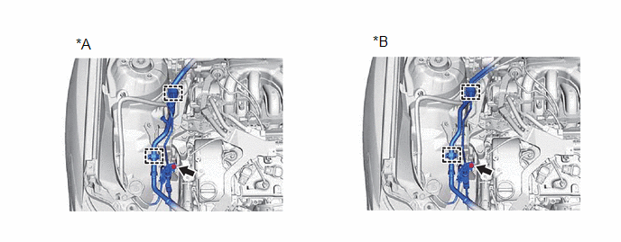
|
*A | Type A |
*B | Type B |
(b) Remove the bolt to separate the suction hose sub-assembly, suction pipe sub-assembly and air conditioning tube and accessory assembly.
(c) Using a safety stand, support the engine assembly with transaxle at the position shown in the illustration.
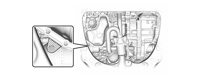
 |
Support Area | - |
- |
NOTICE:
- Make sure to firmly support the weight of the engine assembly and automatic transaxle assembly before removing the engine mounting insulator sub-assembly RH.
- Do not place the safety stand under the oil pan.
(d) Support the engine assembly with automatic transaxle assembly at the position shown in the illustration to stabilize it.
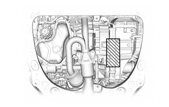
|
|
Support Area |
| (e) Remove the 3 bolts and nut to separate the engine mounting insulator sub-assembly RH from the front No. 1 engine mounting bracket LH. |
|
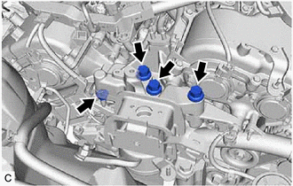
| (f) Remove the nut, 2 bolts and engine mounting insulator sub-assembly RH from the engine mounting spacer and vehicle body. |
|
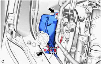
11. DISCONNECT ENGINE WIRE
| (a) Disconnect the water inlet with thermostat sub-assembly connector. |
|
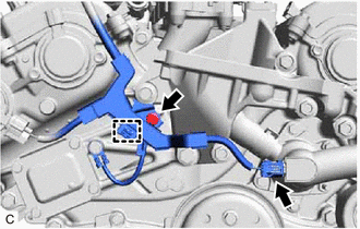
(b) Remove the bolt.
(c) Disengage the clamp to disconnect the engine wire.
12. REMOVE FRONT NO. 1 ENGINE MOUNTING BRACKET LH
Click here
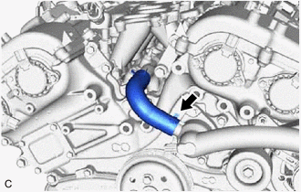
13. DISCONNECT WATER BY-PASS HOSE
| (a) Slide the clip and disconnect the water by-pass hose. |
|
14. REMOVE WATER INLET WITH THERMOSTAT SUB-ASSEMBLY
| (a) Remove the 2 bolts, 2 nuts and water inlet with thermostat sub-assembly. |
|
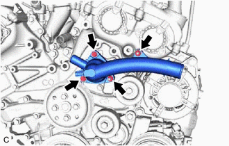
(b) Remove the gasket from the water inlet with thermostat sub-assembly.
READ NEXT:
 Inspection
INSPECTION PROCEDURE 1. INSPECT WATER INLET WITH THERMOSTAT SUB-ASSEMBLY
(a) Check the valve opening. HINT: The valve opening temperature is inscribed on the water inlet with thermostat sub-assembly
Installation
INSTALLATION PROCEDURE 1. INSTALL WATER INLET WITH THERMOSTAT SUB-ASSEMBLY
(a) Install a new gasket to the water inlet with thermostat sub-assembly.
(b) Install the water inlet with thermostat sub
SEE MORE:
Sound Signal Circuit between Radio Receiver and Stereo Component Amplifier
DESCRIPTION The radio and display receiver assembly sends a sound signal to the stereo component amplifier assembly via this circuit.
The sound signal that is sent is amplified by the stereo component amplifier assembly, and then is sent to the speakers.
If there is an open or short in this circ
Reporting safety defects
for U.S. owners
If you believe that your vehicle has a defect which could cause a
crash or could cause injury or death, you should immediately inform
the National Highway Traffic Safety Administration (NHTSA) in addition
to notifying Toyota Motor Sales, U.S.A., Inc. (Toll-free: 1-800-
331-4331).
If NHTSA recei
