Toyota Camry (XV70): Parts Location
PARTS LOCATION
ILLUSTRATION
|
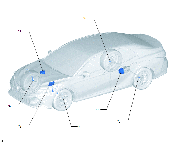
*1 | BRAKE ACTUATOR ASSEMBLY - SKID CONTROL ECU | *2 |
ECM |
| *3 |
FRONT SPEED SENSOR LH |
*4 | FRONT SPEED SENSOR RH |
|
*5 | REAR SKID CONTROL SENSOR LH |
*6 | REAR SKID CONTROL SENSOR RH |
|
*7 | TRANSMISSION COUPLING ASSEMBLY - 4WD LINEAR SOLENOID |
- | - |
ILLUSTRATION
|
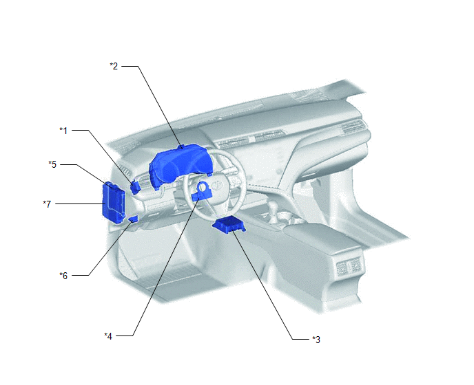
*1 | 4WD ECU ASSEMBLY |
*2 | COMBINATION METER ASSEMBLY - AWD WARNING MESSAGE (MULTI-INFORMATION DISPLAY) |
|
*3 | AIRBAG SENSOR ASSEMBLY - YAW RATE AND ACCELERATION SENSOR |
*4 | STEERING SENSOR |
|
*5 | MAIN BODY ECU (MULTIPLEX NETWORK BODY ECU) |
*6 | DLC3 |
|
*7 | INSTRUMENT PANEL JUNCTION BLOCK ASSEMBLY - ECU-DCC NO. 1 FUSE - ECU-IG1 NO. 2 FUSE |
- | - |
READ NEXT:
 System Diagram
SYSTEM DIAGRAM
How To Proceed With Troubleshooting
CAUTION / NOTICE / HINT
HINT:
Use the following procedure listed to troubleshoot the Dynamic Torque Control AWD System.
*: Use the Techstream.
PROCEDURE
1. VEHICLE BROUGHT TO W
Calibration
CALIBRATION
NOTICE:
Initial AWD functions such as acceleration are sometimes affected unless backup memory is cleared.
When the yaw rate and acceleration sensor (airbag sensor assembly) is
SEE MORE:
Seat belt instructions
for Canadian owners
(in French)
The following is a French explanation of seat belt instructions
extracted from the seat belt section in this manual.
See the seat belt section for more detailed seat belt instructions in
English.
Utilisation correcte des ceintures de sécurité
Déroulez la sangle diagonale
de telle sorte
Pressure Control Solenoid "L" Circuit Short to Ground or Open (P08BA14)
DESCRIPTION Refer to DTC P08BA12. Click here
DTC No. Detection Item
DTC Detection Condition Trouble Area
MIL Memory
Note P08BA14
Pressure Control Solenoid "L" Circuit Short to Ground or Open
While the vehicle is being driven so that gear changes occur,
© 2023-2025 Copyright www.tocamry.com
