Toyota Camry (XV70): Pcv Valve
Components
COMPONENTS
ILLUSTRATION
|
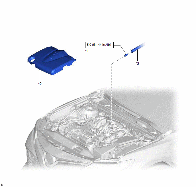
*1 | PCV VALVE (VENTILATION VALVE SUB-ASSEMBLY) |
*2 | V-BANK COVER SUB-ASSEMBLY |
|
*3 | VENTILATION HOSE |
- | - |
.png) |
N*m (kgf*cm, ft.*lbf): Specified torque |
- | - |
Removal
REMOVAL
PROCEDURE
1. REMOVE V-BANK COVER SUB-ASSEMBLY
Click here
.gif)
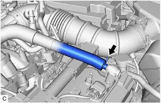
2. DISCONNECT VENTILATION HOSE
| (a) Slide the clip and disconnect the ventilation hose from the PCV valve (ventilation valve sub-assembly). |
|
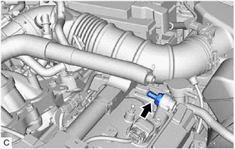
3. REMOVE PCV VALVE (VENTILATION VALVE SUB-ASSEMBLY)
| (a) Using a 22 mm deep socket wrench, remove the PCV valve (ventilation valve sub-assembly) from the cylinder head cover sub-assembly LH. |
|
Inspection
INSPECTION
PROCEDURE
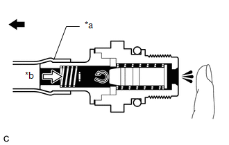
1. INSPECT PCV VALVE (VENTILATION VALVE SUB-ASSEMBLY)
(a) Install a hose to the PCV valve (ventilation valve sub-assembly).
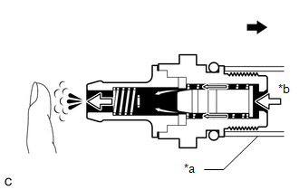
(b) Check PCV valve (ventilation valve sub-assembly) operation.
(1) Blow air into the cylinder head cover sub-assembly LH side, and check that air passes through easily.
|
*a | Hose |
|
*b | Air |
.png) |
Cylinder Head Cover Sub-assembly LH Side |
CAUTION:
Do not suck air through the valve.
Petroleum substances inside the valve are hazardous to your health.
If the result is not as specified, replace the PCV valve (ventilation valve sub-assembly).
(2) Blow air into the intake air surge tank assembly side, and check that air passes through with difficulty.
|
*a | Hose |
|
*b | Air |
|
|
Intake Air Surge Tank Assembly Side |
CAUTION:
Do not suck air through the valve.
Petroleum substances inside the valve are hazardous to your health.
If the result is not as specified, replace the PCV valve (ventilation valve sub-assembly).
(c) Remove the hose from the PCV valve (ventilation valve sub-assembly).
Installation
INSTALLATION
PROCEDURE
1. INSTALL PCV VALVE (VENTILATION VALVE SUB-ASSEMBLY)
(a) Apply a light coat of engine oil to the O-ring.
(b) Using a 22 mm deep socket wrench, install the PCV valve (ventilation valve sub-assembly) to the cylinder head cover sub-assembly LH.
Torque:
5.0 N·m {51 kgf·cm, 44 in·lbf}
NOTICE:
When reusing the PCV valve (ventilation valve sub-assembly), inspect the O-ring.
2. CONNECT VENTILATION HOSE
(a) Connect the ventilation hose to the PCV valve (ventilation valve sub-assembly) and slide the clip to secure it.
3. INSTALL V-BANK COVER SUB-ASSEMBLY
Click here
.gif)
READ NEXT:
 Purge Valve
ComponentsCOMPONENTS ILLUSTRATION
*1 PURGE VALVE (PURGE VSV)
*2 V-BANK COVER SUB-ASSEMBLY
*3 FUEL VAPOR FEED HOSE
*4 NO. 1 FUEL VAPOR FEED HOSE
N*m
Accelerator Pedal
ComponentsCOMPONENTS ILLUSTRATION
*1 ACCELERATOR PEDAL
*2 ACCELERATOR PEDAL PAD
*3 ACCELERATOR PEDAL SENSOR ASSEMBLY
*4 NO. 1 INSTRUMENT PANEL UNDER COVER SUB-ASS
SEE MORE:
Engine maintenance
Drive belt
Drive belt : inspection
Alternator
Drive belt auto-tensioner
Crankshaft pulley
A/c compressor
Water pump
Drive belt
Possible use range
New drive belt range
Ndicator
Warning:
Perform this step when engine is stopped.
Check that the indicator of drive bel
Voice Recognition Microphone Disconnected (B1579)
DESCRIPTION The radio and display receiver assembly, roof console box sub-assembly and telephone microphone assembly are connected to each other using the microphone connection detection signal lines.
This DTC is stored when a microphone connection detection signal line is disconnected.
DTC
