Toyota Camry (XV70): Purge Valve
Components
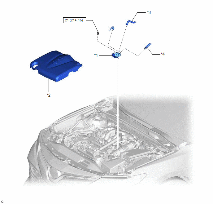
COMPONENTS
ILLUSTRATION
|
*1 | PURGE VALVE (PURGE VSV) |
*2 | V-BANK COVER SUB-ASSEMBLY |
|
*3 | FUEL VAPOR FEED HOSE |
*4 | NO. 1 FUEL VAPOR FEED HOSE |
.png) |
N*m (kgf*cm, ft.*lbf): Specified torque |
- | - |
Removal
REMOVAL
PROCEDURE
1. REMOVE V-BANK COVER SUB-ASSEMBLY
Click here
.gif)
2. REMOVE PURGE VALVE (PURGE VSV)
| (a) Disconnect the purge valve (purge VSV) connector. |
|
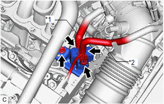
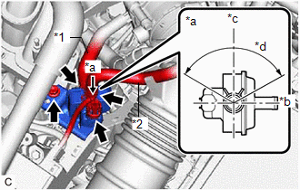
(b) Slide the clip and disconnect the fuel vapor feed hose from the purge valve (purge VSV).
(c) Disconnect the No. 1 fuel vapor feed hose from the purge valve (purge VSV).
(d) Remove the bolt and purge valve (purge VSV) from the intake air surge tank assembly.
Inspection
INSPECTION
PROCEDURE
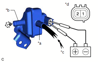
1. INSPECT PURGE VALVE (PURGE VSV)
(a) Measure the resistance according to the value(s) in the table below.
Standard Resistance:
|
Tester Connection | Condition |
Specified Condition |
|---|---|---|
| 1 - 2 |
20°C (68°F) | 23 to 26 Ω |
If the result is not as specified, replace the purge valve (purge VSV).
| (b) Apply battery voltage between the terminals of the purge valve (purge VSV) and check that the following occurs when blowing air into the port (E). OK:
If the result is not as specified, replace the purge valve (purge VSV). |
|
Installation
INSTALLATION
PROCEDURE
1. INSTALL PURGE VALVE (PURGE VSV)
| (a) Install the purge valve (purge VSV) to the intake air surge tank assembly with the bolt. Torque: 21 N·m {214 kgf·cm, 15 ft·lbf} |
|
(b) Connect the No. 1 fuel vapor feed hose to the purge valve (purge VSV).
(c) Connect the fuel vapor feed hose to the purge valve (purge VSV) and slide the clip to secure it.
HINT:
Engage the clip within the area shown in the illustration.
(d) Connect the purge valve (purge VSV) connector.
2. INSTALL V-BANK COVER SUB-ASSEMBLY
Click here .gif)
READ NEXT:
 Accelerator Pedal
ComponentsCOMPONENTS ILLUSTRATION
*1 ACCELERATOR PEDAL
*2 ACCELERATOR PEDAL PAD
*3 ACCELERATOR PEDAL SENSOR ASSEMBLY
*4 NO. 1 INSTRUMENT PANEL UNDER COVER SUB-ASS
SEE MORE:
Installation
INSTALLATION PROCEDURE 1. INSTALL NO. 5 ANTENNA CORD SUB-ASSEMBLY (w/ Manual (SOS) Switch)
(a) Engage the 5 clamps to install the No. 5 antenna cord sub-assembly.
(b) Connect the connector. 2. INSTALL NO. 2 ANTENNA CORD SUB-ASSEMBLY
HINT: Butyl tape and adhesive tape are not available as suppl
Parking Brake Switch Circuit
DESCRIPTION This circuit is from the parking brake switch assembly*1 or skid control ECU (Brake Actuator Assembly)*2 to the radio and display receiver assembly.
*1: w/o Electric Parking Brake System
*2: w/ Electric Parking Brake System
WIRING DIAGRAM w/o Electric Parking Brake System
w/
