Toyota Camry (XV70): Installation
INSTALLATION
PROCEDURE
1. INSTALL NO. 5 ANTENNA CORD SUB-ASSEMBLY (w/ Manual (SOS) Switch)
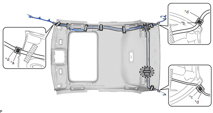
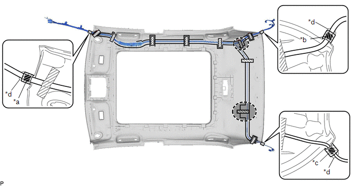
(a) Engage the 5 clamps to install the No. 5 antenna cord sub-assembly.
(b) Connect the connector.
2. INSTALL NO. 2 ANTENNA CORD SUB-ASSEMBLY
HINT:
Butyl tape and adhesive tape are not available as supply parts. If these pieces of tape still have enough adhesion to secure the No. 2 antenna cord sub-assembly to the roof headlining assembly, reuse them. If the adhesive tape and/or the butyl tape is no longer sticky, apply new tape following the procedure below.
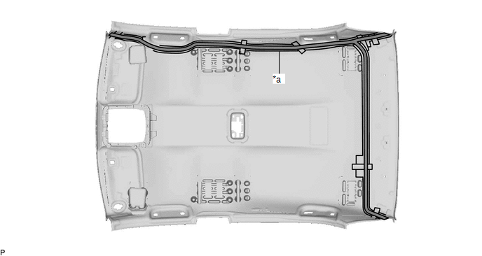
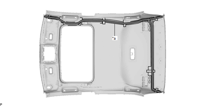
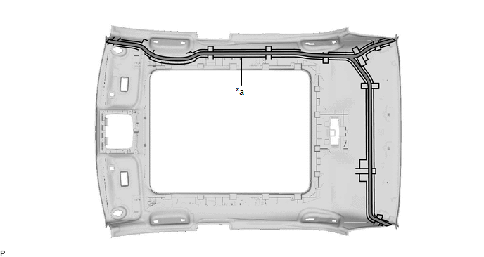
(a) Apply new butyl tape.
for Normal Roof:
|
*a | Marking |
- | - |
 |
Butyl tape | - |
- |
for Moon Roof:
|
*a | Marking |
- | - |
|
|
Butyl tape | - |
- |
for Panoramic Moon Roof:
|
*a | Marking |
- | - |
|
|
Butyl tape | - |
- |
(1) Remove the old butyl tape from the roof headlining assembly.
(2) Prepare an appropriate amount of new butyl tape.
HINT:
Be careful not to touch the adhesive surface.
(3) Apply the butyl tape to the roof headlining assembly while aligning the tape with the markings on the roof headlining assembly.
(4) Peel off the release paper from the butyl tape.
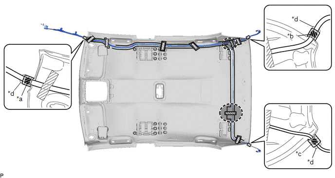
(b) Align the marking tape (A) on the No. 2 antenna cord sub-assembly with the protrusion on the front of the roof headlining assembly and wrap tape around the No. 2 antenna cord sub-assembly and protrusion of the roof headlining assembly.
for Normal Roof:
|
*a | Marking Tape (A) |
*b | Marking Tape (B) |
|
*c | Marking Tape (C) |
*d | Protrusion |
.png) |
Adhesive Tape |
 |
Adjustment Area |
for Moon Roof:
|
*a | Marking Tape (A) |
*b | Marking Tape (B) |
|
*c | Marking Tape (C) |
*d | Protrusion |
|
|
Adhesive Tape |
|
Adjustment Area |
for Panoramic Moon Roof:
|
*a | Marking Tape (A) |
*b | Marking Tape (B) |
|
*c | Marking Tape (C) |
*d | Protrusion |
|
|
Adhesive Tape |
|
Adjustment Area |
(c) Align the marking tape (B) on the No. 2 antenna cord sub-assembly with the protrusion on the rear of the roof headlining assembly and wrap tape around the No. 2 antenna cord sub-assembly and protrusion of the roof headlining assembly.
(d) Align the marking tape (C) on the No. 2 antenna cord sub-assembly with the protrusion on the rear of the roof headlining assembly and wrap tape around the No. 2 antenna cord sub-assembly and protrusion of the roof headlining assembly.
(e) Install the No. 2 antenna cord sub-assembly to the roof headlining assembly.
NOTICE:
- Make sure that there are no gaps between the roof headlining assembly and No. 2 antenna cord sub-assembly, and that the No. 2 antenna cord sub-assembly is not twisted.
- Make sure the No. 2 antenna cord assembly is securely installed. If any part of the No. 2 antenna cord sub-assembly is loose, it will cause an abnormal noise.
HINT:
Secure the extra length of the No. 2 antenna cord sub-assembly in the adjustment area.
(f) Apply the adhesive tape as shown in the illustration to secure the No. 2 antenna cord sub-assembly.
3. INSTALL ROOF HEADLINING ASSEMBLY
Click here
.gif)
4. INSTALL ANTENNA CORD SUB-ASSEMBLY
(a) w/o Navigation Antenna:
(1) Engage the 5 clamps to install the antenna cord sub-assembly.
(b) w/ Navigation Antenna:
(1) Engage the 7 clamps to install the antenna cord sub-assembly.
(2) Engage the 2 claws.
(3) Connect the connector.
5. INSTALL NO. 3 HEATER TO REGISTER DUCT SUB-ASSEMBLY
Click here
6. INSTALL NO. 2 SIDE DEFROSTER NOZZLE DUCT
Click here
7. INSTALL INSTRUMENT PANEL SAFETY PAD SUB-ASSEMBLY
Click here
READ NEXT:
 Components
COMPONENTS ILLUSTRATION
*A for 7 Inch Display
*B for 9 Inch Display
*1 CENTER INSTRUMENT CLUSTER FINISH PANEL ASSEMBLY
*2 CENTER INSTRUMENT CLUSTER FINISH PANEL S
Removal
REMOVAL PROCEDURE 1. PRECAUTION (w/o Navigation System)
NOTICE:
When replacing the radio and display receiver assembly, always replace it with a new one. If a radio and display receiver assembly
SEE MORE:
The keys
The following keys are provided with the vehicle.
Vehicles without a smart key system
Keys
Operating the wireless remote control
function
Key number plate
Vehicles with a smart key system
Electronic keys
Operating the smart key system
Operating the wireless remote
contro
Removal
REMOVAL CAUTION / NOTICE / HINT
The necessary procedures (adjustment, calibration, initialization or registration) that must be performed after parts are removed and installed, or replaced during VVT sensor removal/installation are shown below. Necessary Procedures After Parts Removed/Installed/Re
