Toyota Camry (XV70): Components
COMPONENTS
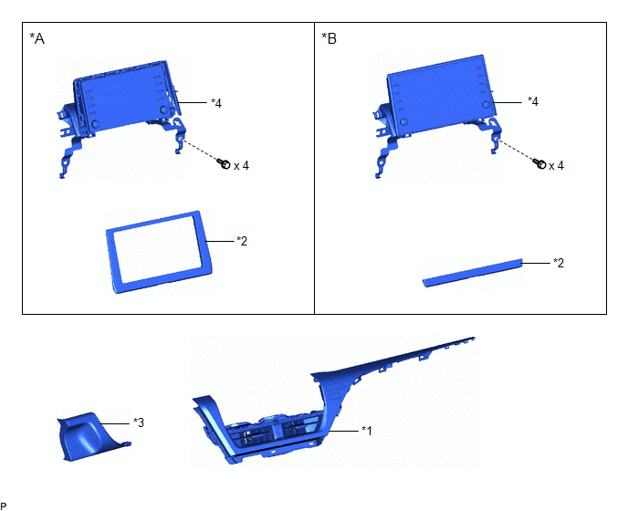
ILLUSTRATION
|
*A | for 7 Inch Display |
*B | for 9 Inch Display |
|
*1 | CENTER INSTRUMENT CLUSTER FINISH PANEL ASSEMBLY |
*2 | CENTER INSTRUMENT CLUSTER FINISH PANEL SUB-ASSEMBLY |
|
*3 | LOWER INSTRUMENT PANEL FINISH PANEL ASSEMBLY |
*4 | RADIO AND DISPLAY RECEIVER ASSEMBLY WITH BRACKET |
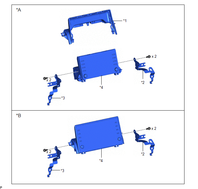
ILLUSTRATION
|
*A | for 7 Inch Display |
*B | for 9 Inch Display |
|
*1 | CENTER INSTRUMENT CLUSTER FINISH UPPER PANEL ASSEMBLY |
*2 | NO. 1 RADIO RECEIVER BRACKET |
|
*3 | NO. 2 RADIO RECEIVER BRACKET |
*4 | RADIO AND DISPLAY RECEIVER ASSEMBLY |
READ NEXT:
 Removal
REMOVAL PROCEDURE 1. PRECAUTION (w/o Navigation System)
NOTICE:
When replacing the radio and display receiver assembly, always replace it with a new one. If a radio and display receiver assembly
Installation
INSTALLATION PROCEDURE 1. PRECAUTION (w/o Navigation System)
NOTICE:
When replacing the radio and display receiver assembly, always replace it with a new one. If a radio and display receiver ass
SEE MORE:
Terminals Of Ecm
TERMINALS OF ECM ECM
HINT: The standard voltage and resistance of each ECM terminal is shown in the table below.
In the table, first follow the information under "Condition". Look under "Terminal No. (Symbol)" for the terminals to be inspected. The standard voltage or resistance between the ter
Installation
INSTALLATION PROCEDURE 1. INSTALL KNOCK CONTROL SENSOR
HINT: Perform "Inspection After Repair" after replacing a knock control sensor.
Click here
(a) Temporarily install the 2 knock control sensors to the cylinder block sub-assembly with the 2 bolts so that the knock control sensor insta
© 2023-2025 Copyright www.tocamry.com
