Toyota Camry (XV70): Removal
REMOVAL
PROCEDURE
1. PRECAUTION (w/o Navigation System)
NOTICE:
- When replacing the radio and display receiver assembly, always replace it with a new one. If a radio and display receiver assembly which was installed to another vehicle is used, the following may occurs:
- A communication malfunction DTC may be stored.
- The radio and display receiver assembly may not operate normally.
NOTICE:
Click here .gif)
2. PRECAUTION (w/ Navigation System)
NOTICE:
- When replacing the radio and display receiver assembly or navigation ECU, always replace it with a new one. If a radio and display receiver assembly or navigation ECU which was installed to another vehicle is used, the following may occur:
- A communication malfunction DTC may be stored.
- The radio and display receiver assembly or navigation ECU may not operate normally.
- After replacing the radio and display receiver assembly, if "New software is not compatible with the system. Contact your dealer." is displayed on the multi-display, update the software of the navigation ECU.
NOTICE:
Click here
3. REMOVE AIR CONDITIONING CONTROL ASSEMBLY
Click here
4. REMOVE LOWER INSTRUMENT PANEL FINISH PANEL ASSEMBLY
Click here
5. REMOVE CENTER INSTRUMENT CLUSTER FINISH PANEL SUB-ASSEMBLY (for 7 Inch Display)
Click here
6. REMOVE CENTER INSTRUMENT CLUSTER FINISH PANEL SUB-ASSEMBLY (for 9 Inch Display)
Click here
7. REMOVE CENTER INSTRUMENT CLUSTER FINISH PANEL ASSEMBLY
Click here
8. REMOVE RADIO AND DISPLAY RECEIVER ASSEMBLY WITH BRACKET (for 7 Inch Display)
| (a) Disengage the clamp. |
|
(b) Remove the 4 bolts.
(c) Disengage the 2 clips and 2 claws as shown in the illustration.
.png) |
Place Hand Here |
.png) |
Remove in this Direction |
(d) Disengage the 2 guides as shown in the illustration.
|
|
Remove in this Direction |
(e) Disconnect each connector and remove the radio and display receiver assembly with bracket.
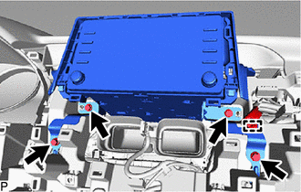
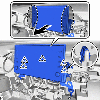
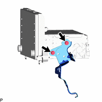
9. REMOVE RADIO AND DISPLAY RECEIVER ASSEMBLY WITH BRACKET (for 9 Inch Display)
| (a) Disengage the clamp. |
|
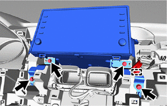
(b) Remove the 4 bolts.
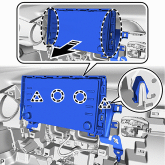
(c) Disengage the 5 clips as shown in the illustration.
|
|
Place Hand Here |
|
|
Remove in this Direction |
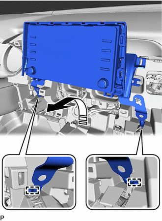
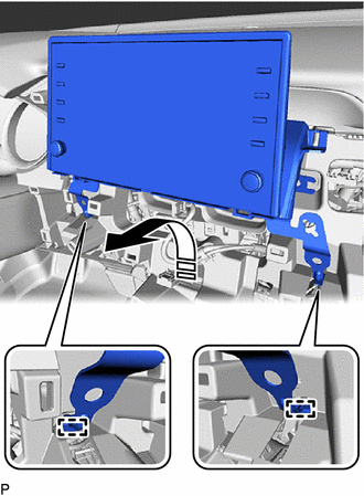
(d) Disengage the 2 guides as shown in the illustration.
|
|
Remove in this Direction |
(e) Disconnect each connector and remove the radio and display receiver assembly with bracket.
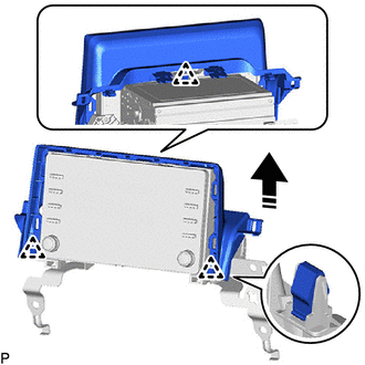
10. REMOVE CENTER INSTRUMENT CLUSTER FINISH UPPER PANEL ASSEMBLY (for 7 Inch Display)
(a) Disengage the 3 clips to remove the center instrument cluster finish upper panel assembly as shown in the illustration.
|
|
Remove in this Direction |
11. REMOVE NO. 2 RADIO RECEIVER BRACKET
| (a) Remove the 2 screws and No. 2 radio receiver bracket. |
|
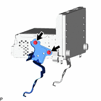
12. REMOVE NO. 1 RADIO RECEIVER BRACKET
| (a) Remove the 2 screws and No. 1 radio receiver bracket. |
|
13. REMOVE RADIO AND DISPLAY RECEIVER ASSEMBLY
READ NEXT:
 Installation
INSTALLATION PROCEDURE 1. PRECAUTION (w/o Navigation System)
NOTICE:
When replacing the radio and display receiver assembly, always replace it with a new one. If a radio and display receiver ass
Components
COMPONENTS ILLUSTRATION
*1 REAR ARMREST ASSEMBLY
*2 REAR DOOR ARMREST COVER SUB-ASSEMBLY
*3 REAR DOOR INNER GLASS WEATHERSTRIP
*4 REAR DOOR NO. 2 SERVICE HOLE COV
SEE MORE:
Repair
REPAIR CAUTION / NOTICE / HINT
HINT:
Use the same procedure for bank 1 and bank 2.
The following procedure is for bank 2.
PROCEDURE 1. REPAIR INTAKE VALVE SEAT
NOTICE:
Repair the intake valve seat while checking the seating position.
Release the cutter gradually to make the i
Problem Symptoms Table
PROBLEM SYMPTOMS TABLE
HINT:
Use the table below to help determine the cause of problem symptoms. If multiple suspected areas are listed, the potential causes of the symptoms are listed in order of probability in the "Suspected Area" column of the table. Check each symptom by checking the susp
