Toyota Camry (XV70): Repair
REPAIR
CAUTION / NOTICE / HINT
HINT:
- Use the same procedure for bank 1 and bank 2.
- The following procedure is for bank 2.
PROCEDURE
1. REPAIR INTAKE VALVE SEAT
NOTICE:
- Repair the intake valve seat while checking the seating position.
- Release the cutter gradually to make the intake valve seat smooth.
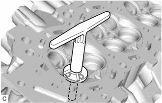
| (a) Using a 45° cutter, resurface the intake valve seat so that the intake valve seat width is more than the standard. |
|
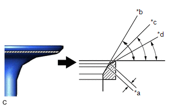
| (b) Using 30° and 60° cutters, correct the intake valve seat so that the intake valve contacts the entire circumference of the intake valve seat. The contact should be in the center of the intake valve seat, and the intake valve seat width should be as specified around the entire circumference of the intake valve seat. Standard Width: 1.1 to 1.5 mm (0.0433 to 0.0591 in.) |
|
(c) Hand lap the intake valve and intake valve seat with an abrasive compound.
(d) Check the intake valve seating position.
2. REPAIR EXHAUST VALVE SEAT
NOTICE:
- Repair the exhaust valve seat while checking the seating position.
- Release the cutter gradually to make the exhaust valve seat smooth.
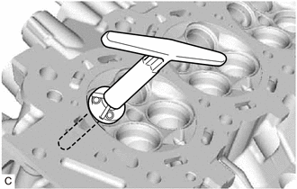
| (a) Using a 45° cutter, resurface the exhaust valve seat so that the exhaust valve seat width is more than the standard. |
|
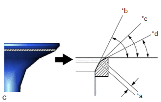
| (b) Using 30° and 75° cutters, correct the exhaust valve seat so that the exhaust valve contacts the entire circumference of the exhaust valve seat. The contact should be in the center of the exhaust valve seat, and the exhaust valve seat width should be as specified around the entire circumference of the exhaust valve seat. Standard Width: 1.1 to 1.5 mm (0.0433 to 0.0591 in.) |
|
(c) Hand lap the exhaust valve and exhaust valve seat with an abrasive compound.
(d) Check the exhaust valve seating position.
READ NEXT:
 Components
COMPONENTS ILLUSTRATION
*A Type A
*B Type B
*1 IGNITION COIL ASSEMBLY
*2 VACUUM PUMP ASSEMBLY
*3 V-RIBBED BELT
*4 GENERATOR ASSEMBLY
*5
Removal
REMOVAL CAUTION / NOTICE / HINT
The necessary procedures (adjustment, calibration, initialization, or registration) that must be performed after parts are removed and installed, or replaced during c
SEE MORE:
Right Front Wheel Speed Sensor Signal Stuck Low (C050623)
DESCRIPTION Refer to DTC C050612 Click here
DTC No. Detection Item
DTC Detection Condition Trouble Area
C050623 Right Front Wheel Speed Sensor Signal Stuck Low
When the vehicle is driven from 0 km/h to 12 km/h (0 mph to 7 mph), the wheel speed is 1.8 km/h (1.1
Dtc Check / Clear
DTC CHECK / CLEAR CHECK DTC (a) Connect the GTS to the DLC3.
(b) Turn the ignition switch to ON. (c) Turn the intuitive parking assist system on.
(d) Turn the GTS on. (e) Enter the following menus: Body Electrical / Clearance Warning / Trouble Codes.
(f) Check for DTCs. Body Electrical > Cl
