Toyota Camry (XV70): Removal
REMOVAL
CAUTION / NOTICE / HINT
The necessary procedures (adjustment, calibration, initialization or registration) that must be performed after parts are removed and installed, or replaced during VVT sensor removal/installation are shown below.
Necessary Procedures After Parts Removed/Installed/Replaced|
Replaced Part or Performed Procedure |
Necessary Procedure | Effect/Inoperative Function when Necessary Procedure not Performed |
Link |
|---|---|---|---|
| Inspection after repair |
|
|
PROCEDURE
1. REMOVE INTAKE AIR SURGE TANK ASSEMBLY
Click here
.gif)
2. REMOVE VVT SENSOR (for Intake Side of Bank 1)
| (a) Disconnect the VVT sensor connector. |
|
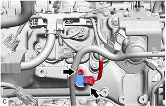
(b) Remove the bolt and VVT sensor from the cylinder head cover sub-assembly.
NOTICE:
If the VVT sensor has been struck or dropped, replace it.
3. REMOVE VVT SENSOR (for Exhaust Side of Bank 1)
| (a) Disconnect the VVT sensor connector. |
|
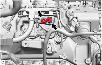
(b) Remove the bolt and VVT sensor from the cylinder head cover sub-assembly.
NOTICE:
If the VVT sensor has been struck or dropped, replace it.
4. REMOVE VVT SENSOR (for Intake Side of Bank 2)
| (a) Disconnect the VVT sensor connector. |
|
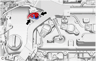
(b) Remove the bolt and VVT sensor from the cylinder head cover sub-assembly LH.
NOTICE:
If the VVT sensor has been struck or dropped, replace it.
5. REMOVE VVT SENSOR (for Exhaust Side of Bank 2)
| (a) Disconnect the VVT sensor connector. |
|
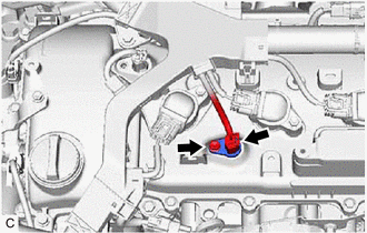
(b) Remove the bolt and VVT sensor from the cylinder head cover sub-assembly LH.
NOTICE:
If the VVT sensor has been struck or dropped, replace it.
READ NEXT:
 Installation
INSTALLATION PROCEDURE 1. INSTALL VVT SENSOR (for Exhaust Side of Bank 2)
(a) Apply a light coat of engine oil to the O-ring of the VVT sensor. NOTICE:
If reusing the VVT sensor, be sure to inspec
Crankshaft Position Sensor
ComponentsCOMPONENTS ILLUSTRATION
*1 CRANKSHAFT POSITION SENSOR
*2 CRANKSHAFT POSITION SENSOR PROTECTOR
N*m (kgf*cm, ft.*lbf): Specified torque
- - Remova
SEE MORE:
Components
COMPONENTS ILLUSTRATION
*1 FRONT FENDER APRON SEAL LH
*2 FRONT FENDER APRON SEAL RH
*3 FRONT WHEEL OPENING EXTENSION PAD LH
*4 FRONT WHEEL OPENING EXTENSION PAD RH
*5 NO. 1 ENGINE UNDER COVER
*6 NO. 2 ENGINE UNDER COVER ASSEMBLY
Rear Differential Side Gear Shaft Oil Seal
ComponentsCOMPONENTS ILLUSTRATION
*1 REAR DRIVE SHAFT OIL SEAL LH
- -
● Non-reusable part
MP grease ReplacementREPLACEMENT CAUTION / NOTICE / HINT
The necessary procedures (adjustment, calibration, initialization, or registration) that must be pe
