Toyota Camry (XV70): Radio Receiver Power Source Circuit
DESCRIPTION
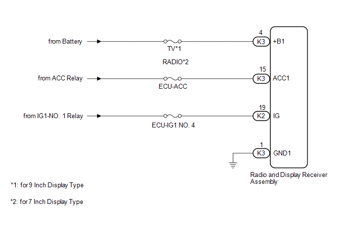
This is the power source circuit to operate the radio and display receiver assembly.
WIRING DIAGRAM
CAUTION / NOTICE / HINT
NOTICE:
Inspect the fuses for circuits related to this system before performing the following procedure.
PROCEDURE
| 1. |
CHECK HARNESS AND CONNECTOR (RADIO AND DISPLAY RECEIVER ASSEMBLY POWER SOURCE) |
(a) Disconnect the K3 and K2 radio and display receiver assembly connectors.
(b) Measure the resistance according to the value(s) in the table below.
Standard Resistance:
|
Tester Connection | Condition |
Specified Condition |
|---|---|---|
|
K3-1 (GND1) - Body ground |
Always | Below 1 Ω |
(c) Measure the voltage according to the value(s) in the table below.
Standard Voltage:
|
Tester Connection | Condition |
Specified Condition |
|---|---|---|
|
K3-4 (+B1) - K3-1 (GND1) |
Always | 11 to 14 V |
|
K3-15 (ACC1) - K3-1 (GND1) |
Ignition switch ACC | 11 to 14 V |
|
K2-19 (IG) - K3-1 (GND1) |
Ignition switch ON | 11 to 14 V |
| OK | .gif) | PROCEED TO NEXT SUSPECTED AREA SHOWN IN PROBLEM SYMPTOMS TABLE |
| NG | | REPAIR OR REPLACE HARNESS OR CONNECTOR |
READ NEXT:
 Components
COMPONENTS ILLUSTRATION
*A for Front Passenger Side
*B for Driver Side
*C w/o Courtesy Light
*D w/ Courtesy Light
*1 COURTESY LIGHT ASSEMBLY
*2
Removal
REMOVAL CAUTION / NOTICE / HINT
HINT:
Use the same procedure for the RH side and LH side.
The following procedure is for the LH side.
PROCEDURE 1. REMOVE FRONT DOOR LOWER FRAME BRACKET G
SEE MORE:
Installation
INSTALLATION CAUTION / NOTICE / HINT
CAUTION: The engine assembly with transaxle is very heavy. Be sure to follow the procedure described in the repair manual, or the engine lifter may suddenly drop or the engine assembly with transaxle may fall off the engine lifter. PROCEDURE
1. INSTALL TORQUE
Inspection
INSPECTION CAUTION / NOTICE / HINT
NOTICE:
When using a vise, place aluminum plates between the part and vise.
When using a vise, do not overtighten it.
PROCEDURE 1. INSPECT REAR DRIVE SHAFT ASSEMBLY
(a) Check that there is no excessive play in the radial direction of the outboar
