Toyota Camry (XV70): Rear Turn Signal Light Bulb
Components
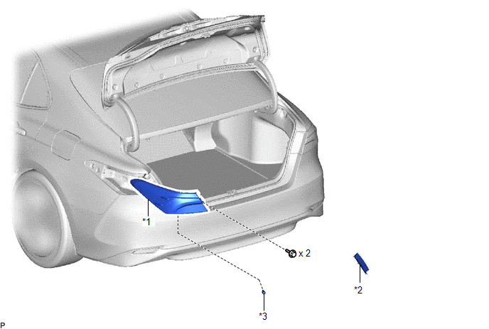
COMPONENTS
ILLUSTRATION
|
*1 | REAR COMBINATION LIGHT ASSEMBLY |
*2 | REAR COMBINATION LIGHT COVER |
|
*3 | REAR TURN SIGNAL LIGHT BULB |
- | - |
Removal
REMOVAL
CAUTION / NOTICE / HINT
HINT:
- Use the same procedure for the RH side and LH side.
- The following procedure is for the LH side.
PROCEDURE
1. REMOVE REAR COMBINATION LIGHT COVER
Click here .gif)
2. SEPARATE REAR COMBINATION LIGHT ASSEMBLY
(a) Apply protective tape around the rear combination light assembly as shown in the illustration.
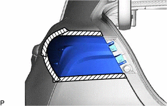
.png) |
Protective Tape |
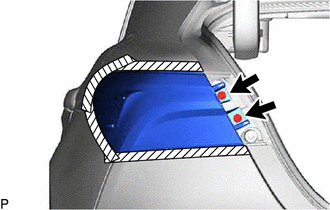
| (b) Remove the 2 screws. |
|
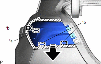
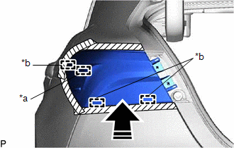
(c) Pull the rear combination light assembly toward the rear of the vehicle as shown in the illustration to disengage the pin and 3 guides and separate the rear combination light assembly.
NOTICE:
To prevent the rear combination light assembly from falling when disengaging the pin and guides, lightly hold the rear combination light assembly.
|
*a | Pin |
|
*b | Guide |
.png) |
Remove in this Direction |
3. REMOVE REAR TURN SIGNAL LIGHT BULB
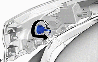
(a) Turn the rear combination light socket and wire with the rear turn signal light bulb as shown in the illustration to disconnect them as a unit.
|
|
Remove in this Direction |
(b) Remove the rear turn signal light bulb from the rear combination light socket and wire.
Installation
INSTALLATION
CAUTION / NOTICE / HINT
HINT:
- Use the same procedure for the RH side and LH side.
- The following procedure is for the LH side.
PROCEDURE
1. INSTALL REAR TURN SIGNAL LIGHT BULB
(a) Install the rear turn signal light bulb to the rear combination light socket and wire.
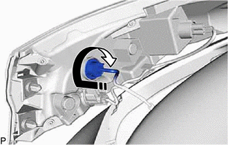
(b) Turn the rear combination light socket and wire with the rear turn signal light bulb as shown in the illustration to connect them as a unit.
.png) |
Install in this Direction |
2. INSTALL REAR COMBINATION LIGHT ASSEMBLY
(a) Engage the 3 guides and pin to temporarily install the rear combination light assembly as shown in the illustration.
|
*a | Pin |
|
*b | Guide |
|
|
Install in this Direction |
(b) Install the rear combination light assembly with the 2 screws.
(c) Remove the protective tape.
3. INSTALL REAR COMBINATION LIGHT COVER
Click here .gif)
READ NEXT:
 Tire And Wheel
ComponentsCOMPONENTS ILLUSTRATION
*A for Steel Wheel
*B except Steel Wheel
*1 WHEEL ASSEMBLY
*2 AXLE HUB NUT
*3 WHEEL CAP
- -
Tig
Transmitter Battery(w/ Smart Key System)
ComponentsCOMPONENTS ILLUSTRATION
*1 TRANSMITTER BATTERY
*2 MECHANICAL KEY
*3 TRANSMITTER HOUSING COVER
*4 TRANSMITTER HOUSING CASE
*5 SMART KEY DOOR CO
Transmitter Battery(w/o Smart Key System)
ComponentsCOMPONENTS ILLUSTRATION
*1 TRANSMITTER BATTERY
*2 TRANSMITTER BATTERY HOUSING COVER
*3 TRANSMITTER HOUSING COVER
*4 TRANSMITTER HOUSING CASE RemovalR
SEE MORE:
Removal
REMOVAL CAUTION / NOTICE / HINT
The necessary procedures (adjustment, calibration, initialization, or registration) that must be performed after parts are removed and installed, or replaced during rear axle carrier sub-assembly removal/installation are shown below. Necessary Procedures After Parts
Telephone And Gps Antenna Cords (for Roof Side)
ComponentsCOMPONENTS ILLUSTRATION
*1 TELEPHONE AND GPS ANTENNA CORD
- - RemovalREMOVAL CAUTION / NOTICE / HINT
The necessary procedures (adjustment, calibration, initialization, or registration) that must be performed after parts are removed and installed, or replaced during
