Toyota Camry (XV70): Removal
REMOVAL
CAUTION / NOTICE / HINT
The necessary procedures (adjustment, calibration, initialization, or registration) that must be performed after parts are removed and installed, or replaced during rear axle carrier sub-assembly removal/installation are shown below.
Necessary Procedures After Parts Removed/Installed/Replaced|
Replaced Part or Performed Procedure |
Necessary Procedure | Effect/Inoperative Function when Necessary Procedure not Performed |
Link |
|---|---|---|---|
| Rear wheel alignment adjustment |
|
|
|
|
Suspension, tires, etc. (The vehicle height changes because of suspension or tire replacement) |
Rear television camera assembly optical axis (Back camera position setting) |
Parking assist monitor system |
|
| Panoramic view monitor system |
|
HINT:
- Use the same procedure for the RH side and LH side.
- The following procedure is for the LH side.
PROCEDURE
1. REMOVE REAR WHEEL
Click here
.gif)
2. REMOVE NO. 2 FLOOR UNDER COVER (for LH Side)
Click here
3. REMOVE NO. 1 FLOOR UNDER COVER (for RH Side)
Click here
4. SEPARATE NO. 2 PARKING BRAKE WIRE ASSEMBLY
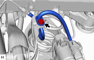
| (a) Disconnect the No. 2 parking brake wire assembly connector from the parking brake actuator assembly. NOTICE:
|
|
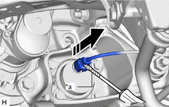
| (b) Using a screwdriver with its tip wrapped with protective tape, disconnect the No. 2 parking brake wire assembly connector from the rear axle hub and bearing assembly. NOTICE: Be careful not to damage the rear axle hub and bearing assembly or connector cover. |
|
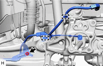
| (c) Remove the nut, disengage the 2 clamps and separate the No. 2 parking brake wire assembly from the rear flexible hose bracket and rear trailing arm assembly. |
|
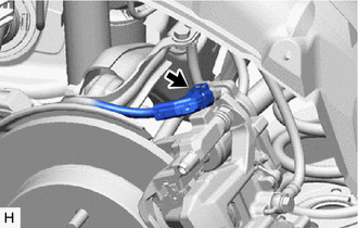
5. SEPARATE REAR FLEXIBLE HOSE
| (a) Remove the bolt and separate the rear flexible hose from the rear flexible hose bracket. |
|
6. SEPARATE REAR DISC BRAKE CALIPER ASSEMBLY
Click here
7. REMOVE REAR DISC
Click here
8. REMOVE REAR AXLE HUB AND BEARING ASSEMBLY
Click here
9. REMOVE REAR FLEXIBLE HOSE BRACKET
| (a) Remove the bolt and rear flexible hose bracket from the rear axle carrier sub-assembly. |
|
10. REMOVE REAR STABILIZER LINK ASSEMBLY
Click here
11. REMOVE REAR COIL SPRING
Click here
12. REMOVE REAR LOWER COIL SPRING INSULATOR
Click here
13. REMOVE REAR NO. 1 SUSPENSION ARM ASSEMBLY
Click here
14. REMOVE REAR AXLE CARRIER SUB-ASSEMBLY
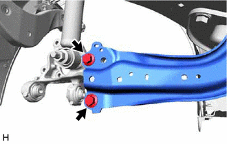
| (a) Loosen the 2 bolts of the rear trailing arm assembly. |
|
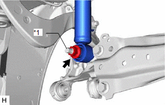
| (b) Loosen the nut of the rear shock absorber assembly. NOTICE: Hold the rear axle carrier pin while rotating the nut. |
|
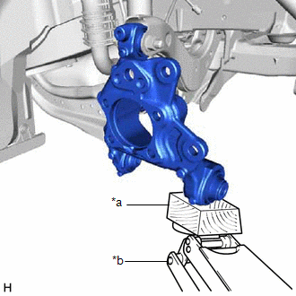
| (c) Using a jack and a wooden block, support the rear axle carrier sub-assembly. NOTICE:
|
|
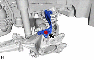
| (d) Loosen the bolt (A). NOTICE: Because the nut has its own stopper, do not turn the nut. Loosen the bolt with the nut secured. |
|
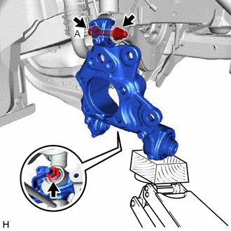
(e) Remove the 2 bolts and separate the rear trailing arm assembly from the rear axle carrier sub-assembly.
(f) Remove the nut and plate washer, and separate the rear shock absorber assembly from the rear axle carrier sub-assembly.
NOTICE:
Hold the rear axle carrier pin while rotating the nut.
(g) Remove the bolt (A), nut and rear axle carrier sub-assembly from the rear upper control arm assembly.
NOTICE:
Because the nut has its own stopper, do not turn the nut. Loosen the bolt with the nut secured.
READ NEXT:
 Installation
INSTALLATION CAUTION / NOTICE / HINT
HINT:
Use the same procedure for the RH side and LH side.
The following procedure is for the LH side.
PROCEDURE 1. TEMPORARILY INSTALL REAR AXLE CARR
Components
COMPONENTS ILLUSTRATION
*A for RH Side
*B for LH Side
*1 NO. 1 FLOOR UNDER COVER
*2 NO. 2 FLOOR UNDER COVER
N*m (kgf*cm, ft.*lbf): Specified torque
SEE MORE:
Removal
REMOVAL CAUTION / NOTICE / HINT
NOTICE: If both left and right front flexible hoses are disconnected at the same time, be sure to place an identification mark on each hose to indicate its installation position.
HINT:
Use the same procedure for the RH side and LH side.
The following proce
Terminals Of Ecu
TERMINALS OF ECU HINT: Check from the rear of the connector while it is connected to the components.
RADIO AND DISPLAY RECEIVER ASSEMBLY
Terminal No. (Symbol) Wiring Color
Terminal Description Condition
Specified Condition
K4-1 (FR+) - K3-1 (GND1)
W - BR Soun
