Toyota Camry (XV70): Terminals Of Ecu
TERMINALS OF ECU
HINT:
Check from the rear of the connector while it is connected to the components.
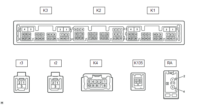
RADIO AND DISPLAY RECEIVER ASSEMBLY
|
Terminal No. (Symbol) | Wiring Color |
Terminal Description | Condition |
Specified Condition |
|---|---|---|---|---|
|
K4-1 (FR+) - K3-1 (GND1) |
W - BR | Sound signal (Right) |
Audio system playing |
A waveform synchronized with sound signals is output |
|
K4-2 (FL+) - K3-1 (GND1) |
B - BR | Sound signal (Left) |
Audio system playing |
A waveform synchronized with sound signals is output |
|
K4-3 (RL+) - K3-1 (GND1) |
Y - BR | Voice signal |
Audio system playing |
A waveform synchronized with sound signals is output |
|
K4-6 (FR-) - K3-1 (GND1) |
R - BR | Sound signal (Right) |
Audio system playing |
A waveform synchronized with sound signals is output |
|
K4-7 (FL-) - K3-1 (GND1) |
G - BR | Sound signal (Left) |
Audio system playing |
A waveform synchronized with sound signals is output |
|
K4-8 (RL-) - K3-1 (GND1) |
BR - BR | Voice signal |
Audio system playing |
A waveform synchronized with sound signals is output |
|
K3-1 (GND1) - Body ground |
BR - Body ground | Ground |
Always | Below 1 V |
|
K3-4 (+B1) - K3-1 (GND1) |
LG - BR*1 R - BR*2 |
Power source (+B) | Always |
11 to 14 V |
|
K3-5 (TX1+) | B |
AVC-LAN communication signal |
- | - |
|
K3-6 (TX1-) | W |
AVC-LAN communication signal |
- | - |
|
K3-15 (ACC1) - K3-1 (GND1) |
GR - BR | Power source (ACC) |
Engine switch off | Below 1 V |
|
Engine switch on (ACC) |
11 to 14 V | |||
|
K3-21 (SW1) - K3-24 (SWG) |
W - L | Steering pad switch signal |
No switch pushed | 2.97 to 3.56 V |
|
Seek+ switch pushed | 0.27 to 0.35 V | |||
|
Seek- switch pushed | 0.86 to 1.03 V | |||
|
Up switch pushed | 0.27 to 0.35 V | |||
|
Down switch pushed | 0.86 to 1.03 V | |||
|
Volume+ switch pushed |
1.51 to 1.79 V | |||
|
Volume- switch pushed |
2.22 to 2.66 V | |||
|
K3-22 (SW2) - K3-24 (SWG) |
LG - L | Steering pad switch signal |
No switch pushed | 2.97 to 3.56 V |
|
MODE switch pushed | 0.27 to 0.35 V | |||
|
On/off hook switch pushed |
1.51 to 1.79 V | |||
|
Voice switch pushed | 2.22 to 2.66 V | |||
|
K3-24 (SWG) - K3-1 (GND1) |
L - BR | Steering pad switch ground |
Always | Below 1 V |
|
K3-25 (MUT1) - K3-1 (GND1) |
BE - BR | Mute signal |
Audio system playing |
2.0 V or higher |
|
Audio system changing modes |
Below 1 V | |||
|
K3-27 (SPD) - K3-1 (GND1) |
LG - BR | Vehicle speed signal |
See "Check Vehicle Signal" in Operation Check Click here
|
- |
| K3-28 (REV) - K3-1 (GND1) |
W - BR | Reverse signal |
See "Check Vehicle Signal" in Operation Check
|
- |
| K2-5 (CNH1) |
L | Local bus communication signal |
- | - |
|
K2-6 (CNL1) | W |
Local bus communication signal |
- | - |
|
K2-13 (CANH) | B |
CAN communication signal |
- | - |
|
K2-14 (CANL) | W |
CAN communication signal |
- | - |
|
K2-15 (ILL+) - K3-1 (GND1) |
G - BR | Illumination signal |
Light control switch off |
Below 1 V |
|
Light control switch in tail or head position |
11 to 14 V | |||
|
K2-16 (ILL-) - K3-1 (GND1) |
BE - BR | Illumination signal |
Light control switch off |
Below 1 V |
|
Light control switch in tail or head position |
Pulse generation | |||
|
K2-19 (IG) - K3-1 (GND1) |
W - BR | Power source (IG) |
Engine switch off | Below 1 V |
|
Engine switch on (IG) |
11 to 14 V | |||
|
K2-20 (PKB) - K3-1 (GND1) |
B - BR | Parking brake signal |
See "Check Vehicle Signal" in Operation Check Click here
|
- |
| K2-21 (MIN+) - K3-1 (GND1) |
SB - BR*1 W - BR*2 |
Microphone voice signal |
See "Check Microphone" in Operation Check Click here
|
- |
| K2-22 (MIN-) - K3-1 (GND1) |
V - BR*1 R - BR *2 |
Microphone voice signal |
See "Check Microphone" in Operation Check Click here
|
- |
|
K2-23 (MACC) - K3-1 (GND1)*2 |
B - BR | Microphone power supply |
Engine switch off | Below 1 V |
|
Engine switch on (ACC) |
4 to 6 V | |||
| K2-24 (SGND) - Body ground |
Shield - Body ground |
Shield ground | Always |
Below 1 V |
|
K2-25 (SNS2) - K3-1 (GND1) |
BE - BR | Microphone connection detection signal |
Always | Below 1 V |
|
K135-1 (USV1) | - |
Power source | - |
- |
| K135-2 (US1-) |
- | Data signal |
- | - |
|
K135-3 (US1+) | - |
Data signal | - |
- |
| K135-4 (UOD1) |
- | Ground |
- | - |
|
K135-5 (USG1) | - |
Shield ground | - |
- |
| r3-1 (US4+) |
- | USB communication line |
- | - |
|
r3-2 (US4-) | - |
USB communication line |
- | - |
|
r3-3 (UGD4) | Shield - Body ground |
Shield ground | Always |
Below 1 Ω |
|
r2-1 (GV2-) | - |
Video signal (Digital) |
- | - |
|
r2-2 (GV2+) | - |
Video signal (Digital) |
- | - |
|
r2-3 (GVG2) - Body ground |
Shield - Body ground |
Shield ground | Always |
Below 1 Ω |
|
K1-7 (SUP) - K3-1 (GND1) |
B - BR | Start up signal |
20 seconds elapse after turning the engine switch on (ACC) |
11 to 14 V |
|
K1-10 (USBV)*1 |
L | DCM (telematics transceiver) power supply |
Engine switch off | Below 1 V |
|
Engine switch on (ACC) |
4.75 to 5.25 V | |||
|
K1-11 (USBG)*1 | GR |
Ground | - |
- |
| K1-12 (SGND) - Body ground |
Shielded - Body ground |
Shield ground | Always |
Below 1 Ω |
|
K1-19 (RST)*3 | R |
- | - |
- |
| K1-22 (SI+) - K3-1 (GND1) |
SB - BR | Voice signal |
Voice guidance sounding |
A waveform synchronized with sound is output |
|
K1-23 (SI-) - K3-1 (GND1) |
V - BR | Voice signal |
Voice guidance sounding |
A waveform synchronized with sound is output |
|
K1-24 (SGND) - K3-1 (GND1) |
Shielded - BR | Shield ground |
Always | Below 1 Ω |
|
K1-25 (MCO+) - K1-26 (MCO-) |
W - B | Microphone voice signal |
See "Check Microphone (DCU)" in Operation Check
|
- |
| K1-26 (MCO-) - K3-1 (GND1) |
B - BR | Microphone voice signal |
See "Check Microphone (DCU)" in Operation Check
|
- |
| K1-28 (REV2) - K3-1 (GND1) |
W - BR | Reverse signal |
Engine running, shift position not in R → in R |
2 V or less → 11 to 14 V |
|
RA-5 (ANT+) - K3-1 (GND1) |
- - BR | Power source of antenna |
Engine switch on (ACC) Radio switch on and FM or AM selected |
11 to 14 V |
- *1: w/ Manual (SOS) Switch
- *2: w/o Manual (SOS) Switch
- *3: It is connected, but not used
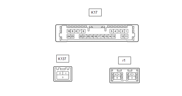
NAVIGATION ECU
|
Terminal No. (Symbol) | Wiring Color |
Terminal Description | Condition |
Specified Condition |
|---|---|---|---|---|
|
K17-6 (VOI+) - K17-23 (GND) |
SB - W-B | Voice signal |
Voice guidance sounding |
A waveform synchronized with sound is output |
|
K17-7 (VOI-) - K17-23 (GND) |
V - W-B | Voice signal |
Voice guidance sounding |
A waveform synchronized with sound is output |
|
K17-8 (SLD1) - Body ground |
Shielded - Body ground |
Shield ground | Always |
Below 1 Ω |
|
K17-9 (SPD) - K17-23 (GND) |
BE - W-B | Vehicle speed signal |
See "Check GPS and Vehicle Sensors" in Operation Check
|
- |
| K17-10 (+B) - K17-23 (GND) |
GR - W-B | Power source (+B) |
Always | 11 to 14 V |
|
K17-13 (MIC+) - K17-23 (GND) |
W - W-B | Microphone voice signal |
See "Microphone Check (MEU)" in Operation Check
|
- |
| K17-14 (MIC-) - Body ground |
B - Body ground | Microphone voice signal |
See "Microphone Check (MEU)" in Operation Check
|
- |
| K17-19 (REV2) - K17-23(GND) |
W - W-B | Reverse signal |
Engine running, shift position not in R → in R |
2 V or less → 11 to 14 V |
|
K17-21 (SUP) - K17-23 (GND) |
B - W-B | Power source (ACC) |
20 seconds elapse after turning the engine switch on (ACC) |
11 to 14 V |
|
K17-22 (RST)*2 | R |
- | - |
- |
| K17-23 (GND) - Body ground |
W-B - Body ground | Ground |
Always | Below 1 Ω |
|
K137-1 (USB4+)*1 | - |
USB communication line |
- | - |
|
K137-2 (USB4-)*1 | - |
USB communication line |
- | - |
|
K137-3 (UGD4) - Body ground*1 |
Shielded - Body ground |
Shield ground | Always |
Below 1 Ω |
|
r1-1 (GVO-) | - |
Video signal (Digital) |
- | - |
|
r1-2 (GVO+) | - |
Video signal (Digital) |
- | - |
|
r1-3 (GVG1) - Body ground |
Shielded - Body ground |
Shield ground | Always |
Below 1 Ω |
|
r1-4 (US4+) | - |
USB communication line |
- | - |
|
r1-5 (US4-) | - |
USB communication line |
- | - |
|
r1-6 (UGD4) - Body ground |
Shielded - Body ground |
Shield ground | Always |
Below 1 Ω |
- *1: w/ Manual (SOS) Switch
- *2: It is connected, but not used
STEREO COMPONENT AMPLIFIER ASSEMBLY
.png)
|
Terminal No. (Symbol) | Wiring Color |
Terminal Description | Condition |
Specified Condition |
|---|---|---|---|---|
|
K14-1 (+B) - K14-3 (GND) |
L - W-B | Power source (+B) |
Always | 11 to 14 V |
|
K14-3 (GND) - Body ground |
W-B - Body ground | Ground |
Always | Below 1 V |
|
K14-8 (WF2+) - K14-3 (GND) |
W - W-B | Sound signal (Woofer) |
Audio system playing |
A waveform synchronized with sound signals is output |
|
K14-9 (RL+) - K14-3 (GND) |
B - W-B | Sound signal (Rear Left) |
Audio system playing |
A waveform synchronized with sound signals is output |
|
K14-10 (WF1+) - K14-3 (GND) |
BE - W-B | Sound signal (Woofer) |
Audio system playing |
A waveform synchronized with sound signals is output |
|
K14-11 (RR+) - K14-3 (GND) |
R - W-B | Sound signal (Rear Right) |
Audio system playing |
A waveform synchronized with sound signals is output |
|
K14-12 (TWL+) - K14-3 (GND) |
B - W-B | Sound signal (Front Left) |
Audio system playing |
A waveform synchronized with sound signals is output |
|
K14-13 (FL+) - K14-3 (GND) |
LG - W-B | Sound signal (Front Left) |
Audio system playing |
A waveform synchronized with sound signals is output |
|
K14-14 (TWR+) - K14-3 (GND) |
W - W-B*1 BE - W-B*2 |
Sound signal (Front Right) |
Audio system playing |
A waveform synchronized with sound signals is output |
|
K14-15 (FR+) - K14-3 (GND) |
BE - W-B | Sound signal (Front Right) |
Audio system playing |
A waveform synchronized with sound signals is output |
|
K14-16 (+B2) - K14-3 (GND) |
B - W-B | Power source (+B) |
Always | 11 to 14 V |
|
K14-18 (GND2) - Body ground |
W-B - Body ground | Ground |
Always | Below 1 V |
|
K14-23 (WF2-) - K14-3 (GND) |
R - W-B | Sound signal (Woofer) |
Audio system playing |
A waveform synchronized with sound signals is output |
|
K14-24 (RL-) - K14-3 (GND) |
LG - W-B | Sound signal (Rear Left) |
Audio system playing |
A waveform synchronized with sound signals is output |
|
K14-25 (WF1-) - K14-3 (GND) |
L - W-B | Sound signal (Woofer) |
Audio system playing |
A waveform synchronized with sound signals is output |
|
K14-26 (RR-) - K14-3 (GND) |
W - W-B | Sound signal (Rear Right) |
Audio system playing |
A waveform synchronized with sound signals is output |
|
K14-27 (TWL-) - K14-3 (GND) |
GR - W-B | Sound signal (Front Left) |
Audio system playing |
A waveform synchronized with sound signals is output |
|
K14-28 (FL-) - K14-3 (GND) |
W - W-B | Sound signal (Front Left) |
Audio system playing |
A waveform synchronized with sound signals is output |
|
K14-29 (TWR-) - K14-3 (GND) |
B - W-B*1 L - W-B*2 |
Sound signal (Front Right) |
Audio system playing |
A waveform synchronized with sound signals is output |
|
K14-30 (FR-) - K14-3 (GND) |
L - W-B | Sound signal (Front Right) |
Audio system playing |
A waveform synchronized with sound signals is output |
|
K10-1 (MUTE) - K14-3 (GND) |
BE - W-B |
Mute signal | Engine switch on (ACC) Audio system playing |
2.0 V or higher |
|
Audio system changing modes |
Below 1 V | |||
|
K10-2 (L-) - K14-3 (GND) |
G - W-B | Sound signal (Left) |
Audio system playing |
A waveform synchronized with sound signals is output |
|
K10-3 (L+) - K14-3 (GND) |
B - W-B | Sound signal (Left) |
Audio system playing |
A waveform synchronized with sound signals is output |
|
K10-4 (R-) - K14-3 (GND) |
R - W-B | Sound signal (Right) |
Audio system playing |
A waveform synchronized with sound signals is output |
|
K10-5 (R+) - K14-3 (GND) |
W - W-B | Sound signal (Right) |
Audio system playing |
A waveform synchronized with sound signals is output |
|
K10-6 (SLD) - Body ground |
Shield - Body ground |
Shield ground | Always |
Below 1 V |
|
K10-7 (TX-) | W |
AVC-LAN communication signal |
- | - |
|
K10-8 (TX+) | B |
AVC-LAN communication signal |
- | - |
|
K10-11 (SPD) - K14-3 (GND) |
G - W-B | Vehicle speed signal |
Engine switch on (IG) Wheel being rotated |
Pulse generation |
|
K10-12 (ACC) - K14-3 (GND) |
LG - W-B |
Power source (ACC) | Engine switch off |
Below 1 V |
|
Engine switch on (ACC) |
11 to 14 V | |||
|
K10-14 (II1-) - K14-3 (GND) |
BR - W-B | Voice signal |
Voice guidance sounding |
A waveform synchronized with voice signals is output |
|
K10-15 (II1+) - K14-3 (GND) |
Y - W-B | Voice signal |
Voice guidance sounding |
A waveform synchronized with voice signals is output |
|
K10-18 (SLD1) - Body ground |
Shield - Body ground |
Shield ground | Always |
Below 1 V |
|
K10-24 (TMUT) - Body ground*1 |
BE - Body ground |
Mute signal | Engine switch on (ACC) Audio system playing |
2.0 V or higher |
|
Emergency call mode | Below 1 V |
- *1: w/ Manual (SOS) Switch
- *2: w/o Manual (SOS) Switch
DCM (TELEMATICS TRANSCEIVER) (w/ Manual (SOS) Switch)
Click here
.gif)
COMBINATION METER ASSEMBLY
Click here
HEADUP DISPLAY (METER MIRROR SUB-ASSEMBLY) (w/ Headup Display System)
Click here
SKID CONTROL ECU (BRAKE ACTUATOR ASSEMBLY)
Click here
READ NEXT:
 Dtc Check / Clear
DTC CHECK / CLEAR CHECK DTC (CHECK USING TECHSTREAM)
(a) Connect the Techstream to the DLC3. (b) Turn the engine switch on (IG) and wait for 90 seconds.
(c) Turn the Techstream on. (d) Enter the f
Freeze Frame Data
FREEZE FRAME DATA CHECK FREEZE FRAME DATA (a) Connect the Techstream to the DLC3.
(b) Turn the engine switch on (IG). (c) Turn the Techstream on.
(d) Enter the following menus: Body Electrical / N
Data List / Active Test
DATA LIST / ACTIVE TEST DATA LIST NOTICE:
In the table below, the values listed under "Normal Condition" are reference values. Do not depend solely on these reference values when deciding whether a
SEE MORE:
Reassembly
REASSEMBLY PROCEDURE 1. INSTALL CYLINDER BLOCK WATER JACKET SPACER
(a) Install the cylinder block water jacket spacer and cylinder block water jacket spacer LH to the cylinder block sub-assembly.
NOTICE: Firmly press the cylinder block water jacket spacer into the cylinder block sub-assembl
Cellular Phone Registration Failure
CAUTION / NOTICE / HINT
NOTICE:
Depending on the parts that are replaced during vehicle inspection or maintenance, performing initialization, registration or calibration may be needed. Refer to Precaution for Navigation System.
Click here
When replacing the radio and display receiver
