Toyota Camry (XV70): Reassembly
REASSEMBLY
PROCEDURE
1. BEARING POSITION
Check bearing position and installation direction.
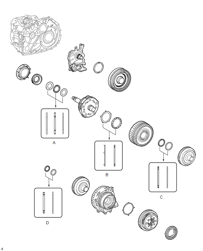
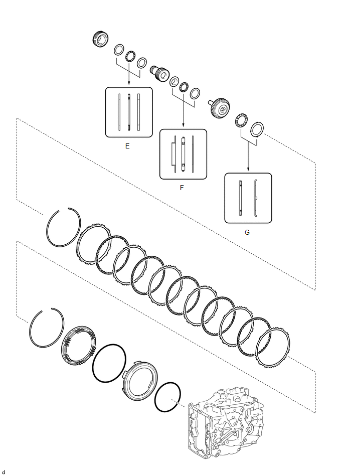
Thrust Needle Roller Bearing and Bearing Race Diameter:
|
Mark | Front Side Thrust Bearing Race Diameter Inside / Outside mm (in.) | Thrust Bearing Diameter Inside / Outside mm (in.) | Rear Side Thrust Bearing Race Diameter Inside / Outside mm (in.) |
|---|---|---|---|
| A |
32.6 (1.28) / 54.2 (2.13) |
31.7 (1.25) / 52.3 (2.06) |
31.7 (1.25) / 52.3 (2.06) |
|
B | 59.8 (2.35) / 77.0 (3.03) |
58.3 (2.30) / 75.0 (2.95) |
- |
| C |
- | 39.2 (1.54) / 52.6 (2.07) |
38.1 (1.50) / 50.2 (1.98) |
|
D | - |
33.3 (1.31) / 46.3 (1.82) |
34.2 (1.35) / 47.3 (1.86) |
|
E | 34.4 (1.35) / 48.7 (1.92) |
33.2 (1.31) / 47.7 (1.88) |
33.2 (1.31) / 47.7 (1.88) |
|
F | 25.58 (1.01) / 43.7 (1.72) |
24.2 (0.953) / 43.7 (1.72) |
24.2 (0.953) / 43.7 (1.72) |
|
G | - |
50.5 (1.99) / 74.5 (2.93) |
52.8 (2.08) / 76.4 (3.01) |
2. INSTALL AUTOMATIC TRANSMISSION CASE STRAIGHT PIN
NOTICE:
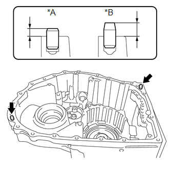
It is not necessary to remove the automatic transmission case straight pins unless they are being replaced.
.png)
.png) |
Serial Number |
HINT:
The component manufacturer (AISIN AW or TMMWV (TOYOTA)) can be determined based on the serial number as described in the following table.
|
Serial Number | Factory |
|---|---|
|
##6######## | AISIN AW |
|
##A######## | TMMWV |
| (a) Using a plastic hammer, tap in 2 new automatic transmission case straight pins to the specified protrusion height. Protrusion Height: for AISIN AW Made 10.7 to 11.3 mm (0.421 to 0.445 in.) for TMMWV Made 7.0 to 8.0 mm (0.276 to 0.315 in.) |
|
3. INSTALL COUNTER DRIVEN GEAR FRONT TAPERED ROLLER BEARING (INNER RACE)
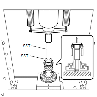
| (a) Using SST and a press, install a new counter driven gear front tapered roller bearing (inner race) to the pinion and counter driven gear sub-assembly. SST: 09950-60011 09951-00550 SST: 09950-70010 09951-07150 NOTICE: Be sure to install the counter driven gear front tapered roller bearing (inner race) so that there is no clearance between the counter driven gear front tapered roller bearing (inner race) and the pinion and counter driven gear sub-assembly. If there is any clearance, the turning torque of the pinion and counter driven gear sub-assembly cannot be measured correctly. |
|
4. INSTALL COUNTER DRIVEN GEAR FRONT TAPERED ROLLER BEARING (OUTER RACE)
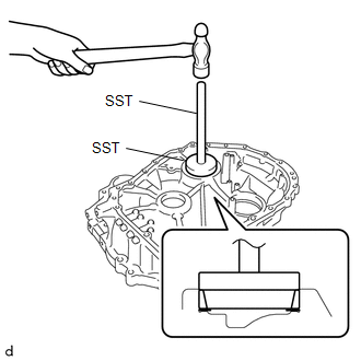
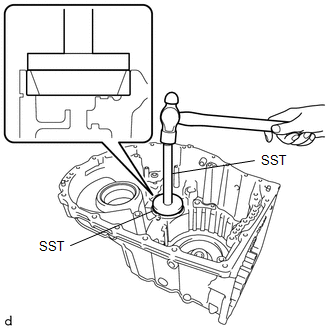
| (a) Using SST and a hammer, install a new counter driven gear front tapered roller bearing (outer race) and pinion and counter driven gear shim to the transaxle housing. SST: 09950-60021 09951-00780 SST: 09950-70010 09951-07150 NOTICE: Be sure to install the counter driven gear front tapered roller bearing (outer race) so that there is no clearance between the counter driven gear front tapered roller bearing (outer race), pinion and counter driven gear shim and the transaxle housing. If there is any clearance, the turning torque of the pinion and counter driven gear sub-assembly cannot be measured correctly. |
|
5. INSTALL COUNTER DRIVEN GEAR REAR TAPERED ROLLER BEARING (INNER RACE)
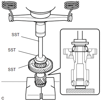
| (a) Using SST and a press, install a new counter driven gear rear tapered roller bearing (inner race) to the pinion and counter driven gear sub-assembly. SST: 09506-30012 SST: 09950-60011 09951-00420 09951-00550 SST: 09950-70010 09951-07150 NOTICE: Be sure to install the counter driven gear rear tapered roller bearing (inner race) so that there is no clearance between the counter driven gear rear tapered roller bearing (inner race) and the pinion and counter driven gear sub-assembly. If there is any clearance, the turning torque of the pinion and counter driven gear sub-assembly cannot be measured correctly. |
|
6. INSTALL COUNTER DRIVEN GEAR REAR TAPERED ROLLER BEARING (OUTER RACE)
| (a) Using SST and a hammer, install a new counter driven gear rear tapered roller bearing (outer race) to the automatic transaxle case sub-assembly. SST: 09950-60021 09951-00680 SST: 09950-70010 09951-07150 NOTICE: Be sure to install the counter driven gear rear tapered roller bearing (outer race) so that there is no clearance between the counter driven gear rear tapered roller bearing (outer race) and the automatic transaxle case sub-assembly. If there is any clearance, the turning torque of the pinion and counter driven gear sub-assembly cannot be measured correctly. |
|
7. ADJUST FRONT DIFFERENTIAL CASE TAPERED ROLLER BEARING PRELOAD
.png)
.png) |
Serial Number |
HINT:
The component manufacturer (AISIN AW or TMMWV (TOYOTA)) can be determined based on the serial number as described in the following table.
|
Serial Number | Factory |
|---|---|
|
##6######## | AISIN AW |
|
##A######## | TMMWV |
(a) Remove any remaining seal packing from the contact surfaces of the transaxle housing and automatic transaxle case sub-assembly.
(b) Coat the front differential case front tapered roller bearing (inner race) and the front differential case rear tapered roller bearing (inner race) with a sufficient amount of Toyota Genuine ATF WS.
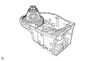
| (c) Install the differential case assembly to the automatic transaxle case sub-assembly. |
|
| (d) Install the transaxle housing to the automatic transaxle case sub-assembly with the 21 bolts (A and B). Torque: 29.4 N |

