Toyota Camry (XV70): Reassembly
REASSEMBLY
CAUTION / NOTICE / HINT
HINT:
- Use the same procedure for bank 1 and bank 2.
- The following procedure is for bank 2.
PROCEDURE
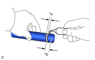
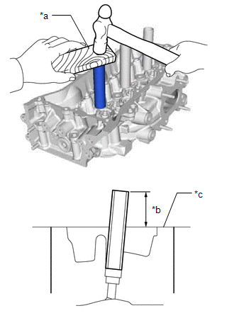
1. INSTALL SPARK PLUG TUBE
HINT:
When using a new cylinder head LH, the spark plug tubes must be replaced.
| (a) Apply adhesive to a new spark plug tube as shown in the illustration. Adhesive: Toyota Genuine Adhesive 1324, Three Bond 1324 or equivalent Standard Application Width: 1.0 to 3.0 mm (0.0394 to 0.118 in.) NOTICE: Install the spark plug tube within 3 minutes of applying adhesive. |
|
| (b) Using a hammer and wooden block, tap in the 3 spark plug tubes to the specified protrusion height. Standard Protrusion Height: 73 mm (2.87 in.) NOTICE:
|
|
2. INSTALL NO. 3 STRAIGHT SCREW PLUG
| (a) Using a 10 mm hexagon socket wrench, install 4 new cylinder head screw plug gaskets and the 4 No. 3 straight screw plugs to the cylinder head LH. Torque: 65 N·m {663 kgf·cm, 48 ft·lbf} NOTICE:
|
|
.png)
3. INSTALL NO. 2 STRAIGHT SCREW PLUG
| (a) Using a 14 mm hexagon wrench, install a new cylinder head screw plug gasket and the No. 2 straight screw plug to the cylinder head LH. Torque: 80 N·m {816 kgf·cm, 59 ft·lbf} |
|
.png)
4. INSTALL NO. 1 STRAIGHT SCREW PLUG
(a) Apply adhesive to the 2 No. 1 straight screw plugs.
Adhesive:
Toyota Genuine Adhesive 1324, Three Bond 1324 or equivalent
NOTICE:
Install the 2 No. 1 straight screw plugs within 3 minutes of applying adhesive.
| (b) Using a 10 mm hexagon socket wrench, install 2 new water hole gaskets and the 2 No. 1 straight screw plugs to the cylinder head LH. Torque: 44 N·m {449 kgf·cm, 32 ft·lbf} |
|
.png)
5. INSTALL VALVE SPRING SEAT
(a) Install the 12 valve spring seats to the cylinder head LH.
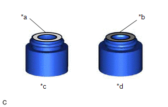
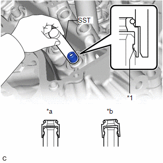
6. INSTALL INTAKE VALVE STEM OIL SEAL
| (a) Apply a light coat of engine oil to a new intake valve stem oil seal. NOTICE: Make sure to install each valve stem oil seal to the correct side. Installing an intake valve stem oil seal to the exhaust side or installing an exhaust valve stem oil seal to the intake side can cause installation problems later. HINT: The intake valve stem oil seals are gray and the exhaust valve stem oil seals are black. |
|
| (b) Using SST, push in the 6 intake valve stem oil seals to the intake valve guide bush. SST: 09201-41020 NOTICE:
|
|
7. INSTALL EXHAUST VALVE STEM OIL SEAL
HINT:
Use the same procedure as for the intake side.
8. INSTALL EXHAUST VALVE
|
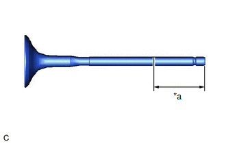
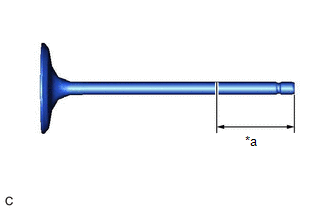
(a) Sufficiently apply engine oil to the tip area of the exhaust valve shown in the illustration. |
|
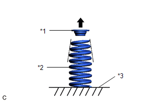
(b) Install the 6 exhaust valves, 6 inner compression springs and 6 valve spring retainers to the cylinder head LH.
|
*1 | Valve Spring Retainer |
|
*2 | Inner Compression Spring |
|
*3 | Cylinder Head LH |
.png) |
Top Side |
NOTICE:
- Install the inner compression spring with its tapered side facing upward (towards the valve spring retainer).
- Install the same parts in the same combination to their original locations.
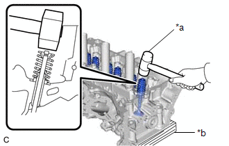
| (c) Using SST and wooden blocks, compress the inner compression spring and install the 6 valve spring retainer locks to the valve spring retainer. SST: 09202-70020 09202-01010 09202-01020 SST: 09202-00021 NOTICE: Install the same parts in the same combination to their original locations. |
|
.png)
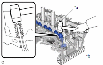
| (d) Using a plastic hammer, lightly tap the valve stem tip to ensure a proper fit. NOTICE:
|
|
9. INSTALL INTAKE VALVE
|
(a) Sufficiently apply engine oil to the tip area of the intake valve shown in the illustration. |
|
(b) Install the 6 intake valves, 6 inner compression springs and 6 valve spring retainers to the cylinder head LH.
|
*1 | Valve Spring Retainer |
|
*2 | Inner Compression Spring |
|
*3 | Cylinder Head LH |
|
|
Top Side |
NOTICE:
- Install the inner compression spring with its tapered side facing upward (towards the valve spring retainer).
- Install the same parts in the same combination to their original locations.
| (c) Using SST and wooden blocks, compress the inner compression spring and install the 6 valve spring retainer locks to the valve spring retainer. SST: 09202-70020 09202-01010 09202-01020 SST: 09202-00021 NOTICE: Install the same parts in the same combination to their original locations. |
|
.png)
| (d) Using a plastic hammer, lightly tap the valve stem tip to ensure a proper fit. NOTICE:
|
|
READ NEXT:
 Repair
REPAIR CAUTION / NOTICE / HINT
HINT:
Use the same procedure for bank 1 and bank 2.
The following procedure is for bank 2.
PROCEDURE 1. REPAIR INTAKE VALVE SEAT
NOTICE:
Repair the i
Components
COMPONENTS ILLUSTRATION
*A Type A
*B Type B
*1 IGNITION COIL ASSEMBLY
*2 VACUUM PUMP ASSEMBLY
*3 V-RIBBED BELT
*4 GENERATOR ASSEMBLY
*5
SEE MORE:
Sound Signal Circuit between Radio Receiver and Stereo Component Amplifier
DESCRIPTION The radio and display receiver assembly sends a sound signal to the stereo component amplifier assembly via this circuit.
The sound signal that is sent is amplified by the stereo component amplifier assembly, and then is sent to the speakers.
If there is an open or short in this circ
Internal Control Module Throttle Position Performance Internal Electronic Failure (P060E49,P061E49)
MONITOR DESCRIPTION The ECM monitors the signals received from the No. 1 throttle position sensor and stop light switch assembly. As the ECM monitors the STP signal of the stop light switch assembly and the VTA1 signal of the No. 1 throttle position sensor, if these signals do not correlate, a DTC w
