Toyota Camry (XV70): Relay
On-vehicle Inspection
ON-VEHICLE INSPECTION
PROCEDURE
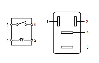
1. INSPECT NO. 1 ELECTRONIC FUEL INJECTION MAIN RELAY (EFI-MAIN NO. 1)
| (a) Measure the resistance according to the value(s) in the table below. Standard Resistance:
If the result is not as specified, replace the No. 1 electronic fuel injection main relay (EFI-MAIN NO. 1). |
|
2. INSPECT NO. 2 ELECTRONIC FUEL INJECTION MAIN RELAY (EFI-MAIN NO. 2)
| (a) Measure the resistance according to the value(s) in the table below. Standard Resistance:
If the result is not as specified, replace the No. 2 electronic fuel injection main relay (EFI-MAIN NO. 2). |
|
3. INSPECT AIR FUEL RATIO SENSOR HEATER RELAY (EFI-MAIN NO. 3)
| (a) Measure the resistance according to the value(s) in the table below. Standard Resistance:
If the result is not as specified, replace the air fuel ratio sensor heater relay (EFI-MAIN NO. 3). |
|
4. INSPECT EFI INJECTION RELAY (D INJ)
| (a) Measure the resistance according to the value(s) in the table below. Standard Resistance:
If the result is not as specified, replace the EFI injector relay (D INJ). |
|
5. INSPECT NO. 2 IGNITION RELAY (IG2 NO. 1)
| (a) Measure the resistance according to the value(s) in the table below. Standard Resistance:
If the result is not as specified, replace the No. 2 ignition relay (IG2 NO. 1). |
|
READ NEXT:
 Precaution
PRECAUTION INITIALIZATION
NOTICE:
Before replacing the ECM, refer to Registration.
Click here
Perform Registration (VIN registration) after replacing the ECM.
Click here
Perform L
Definition Of Terms
DEFINITION OF TERMS
Term Definition
Monitor Description Description of what the ECM monitors and how it detects malfunctions (monitoring purpose and details).
Related DTCs
SEE MORE:
Mute Signal Circuit between Stereo Component Amplifier and Telematics Transceiver
DESCRIPTION The DCM (telematics transceiver) sends a mute signal to the stereo component amplifier assembly.
The stereo component amplifier assembly controls the volume according to the mute signal from the DCM (telematics transceiver). WIRING DIAGRAM
CAUTION / NOTICE / HINT
NOTICE:
Depen
Throttle Actuator "A" Control System Actuator Stuck Open (P211172,P211173)
DESCRIPTION The throttle actuator is operated by the ECM, and opens and closes the throttle valve using gears. The opening angle of the throttle valve is detected by the throttle position sensor, which is mounted on the throttle body with motor assembly. The throttle position sensor provides feedbac
