Toyota Camry (XV70): Mute Signal Circuit between Stereo Component Amplifier and Telematics Transceiver
DESCRIPTION
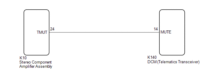
The DCM (telematics transceiver) sends a mute signal to the stereo component amplifier assembly.
The stereo component amplifier assembly controls the volume according to the mute signal from the DCM (telematics transceiver).
WIRING DIAGRAM
CAUTION / NOTICE / HINT
NOTICE:
- Depending on the parts that are replaced during vehicle inspection or maintenance, performing initialization, registration or calibration may be needed. Refer to Precaution for Navigation System.
Click here
.gif)
- Before replacing the DCM (telematics transceiver), refer to Registration.
Click here
PROCEDURE
|
1. | INSPECT DCM (TELEMATICS TRANSCEIVER) |
| (a) Measure the voltage according to the value(s) in the table below. Standard Voltage:
|
|
| OK | .gif) | PROCEED TO NEXT SUSPECTED AREA SHOWN IN PROBLEM SYMPTOMS TABLE
|
|
.gif)
| 2. |
CHECK HARNESS AND CONNECTOR (STEREO COMPONENT AMPLIFIER ASSEMBLY - DCM (TELEMATICS TRANSCEIVER)) |
(a) Disconnect the K10 stereo component amplifier assembly connector.
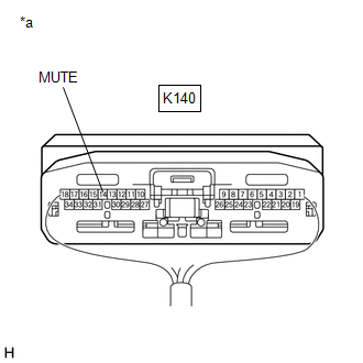
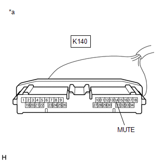
(b) Disconnect the K140 DCM (telematics transceiver) connector.
(c) Measure the resistance according to the value(s) in the table below.
Standard Resistance:
|
Tester Connection | Condition |
Specified Condition |
|---|---|---|
|
K10-24 (TMUT) - K140-14 (MUTE) |
Always | Below 1 Ω |
|
K10-24 (TMUT) or K140-14 (MUTE) - Body ground |
Always | 10 kΩ or higher |
| NG | | REPAIR OR REPLACE HARNESS OR CONNECTOR |
|
| 3. |
INSPECT STEREO COMPONENT AMPLIFIER ASSEMBLY |
(a) Disconnect the K140 DCM (telematics transceiver) connector.
| (b) Measure the voltage according to the value(s) in the table below. Standard Voltage:
|
|
| OK | | REPLACE DCM (TELEMATICS TRANSCEIVER)
|
| NG | | REPLACE STEREO COMPONENT AMPLIFIER ASSEMBLY
|
READ NEXT:
 AVC-LAN Circuit
DESCRIPTION Each unit of the navigation system connected to the AVC-LAN (communication bus) transmits signals via AVC-LAN communication.
If a short to +B or short to ground occurs in an AVC-LAN comm
Vehicle Speed Signal Circuit between Navigation ECU and Combination Meter
DESCRIPTION The navigation ECU receives a vehicle speed signal from the combination meter assembly.
HINT:
A voltage of 12 V or 5 V is output from each ECU and then input to the combination meter
Vehicle Speed Signal Circuit between Stereo Component Amplifier and Combination Meter
DESCRIPTION The stereo component amplifier assembly receives a vehicle speed signal from the combination meter assembly to control the ASL function.
HINT:
A voltage of 12 V or 5 V is output from
SEE MORE:
Seat belts
Make sure that all occupants are wearing their seat belts before
driving the vehicle.
Correct use of the seat belts
Extend the shoulder belt so that
it comes fully over the shoulder,
but does not come into contact
with the neck or slide off the
shoulder.
Position the lap belt as low
On-vehicle Inspection
ON-VEHICLE INSPECTION PROCEDURE
1. OPERATION CHECK (a) Slide the clip and disconnect the union to check valve hose from the vacuum pump assembly.
(b) Connect the hose of the vacuum gauge to the vacuum pump assembly.
*a Vacuum Gauge
*b Plug
