Toyota Camry (XV70): Vehicle Speed Signal Circuit between Navigation ECU and Combination Meter
DESCRIPTION
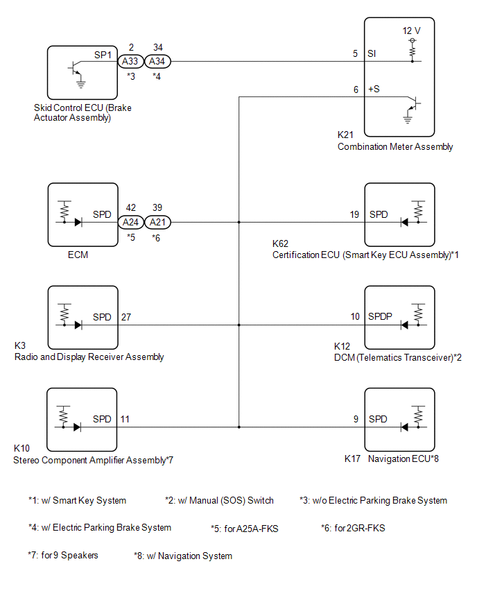
The navigation ECU receives a vehicle speed signal from the combination meter assembly.
HINT:
- A voltage of 12 V or 5 V is output from each ECU and then input to the combination meter assembly. The signal is changed to a pulse signal at the transistor in the combination meter assembly. Each ECU controls its respective systems based on this pulse signal.
- If a short occurs in any of the ECUs or in the wire harness connected to an ECU, all systems in the following diagram will not operate normally.
WIRING DIAGRAM
PROCEDURE
| 1. |
CHECK COMBINATION METER ASSEMBLY (OUTPUT WAVEFORM) |
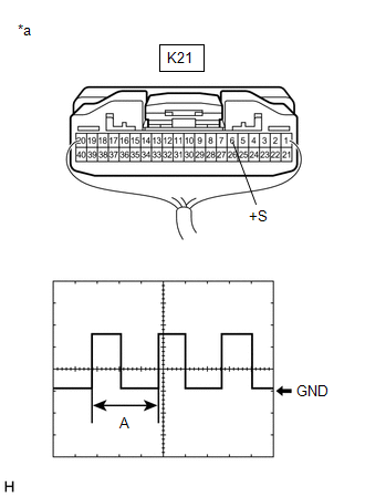
| (a) Check the output waveform. (1) Remove the combination meter assembly with the connector(s) still connected. (2) Connect an oscilloscope to terminal K21-6 (+S) and body ground. (3) Turn the engine switch on (IG). (4) Turn a wheel slowly. (5) Check the signal waveform according to the condition(s) in the table below.
OK: The waveform is similar to that shown in the illustration. HINT: When the system is functioning normally, one wheel revolution generates 4 pulses. As the vehicle speed increases, the width indicated by (A) in the illustration narrows. |
|
| NG | .gif) | GO TO METER / GAUGE SYSTEM
|
.gif)
|
.gif)
| 2. |
CHECK HARNESS AND CONNECTOR (NAVIGATION ECU - COMBINATION METER ASSEMBLY) |
(a) Disconnect the K17 navigation ECU connector.
(b) Disconnect the K21 combination meter assembly connector.
(c) Measure the resistance according to the value(s) in the table below.
Standard Resistance:
|
Tester Connection | Condition |
Specified Condition |
|---|---|---|
|
K17-9 (SPD) - K21-6 (+S) |
Always | Below 1 Ω |
| OK | | PROCEED TO NEXT SUSPECTED AREA SHOWN IN PROBLEM SYMPTOMS TABLE
|
| NG | | REPAIR OR REPLACE HARNESS OR CONNECTOR |
READ NEXT:
 Vehicle Speed Signal Circuit between Stereo Component Amplifier and Combination Meter
DESCRIPTION The stereo component amplifier assembly receives a vehicle speed signal from the combination meter assembly to control the ASL function.
HINT:
A voltage of 12 V or 5 V is output from
Reverse Signal Circuit
DESCRIPTION The radio and display receiver assembly receives a reverse signal from the BKUP LP relay. WIRING DIAGRAM
PROCEDURE
1.
CHECK BACK-UP LIGHT (a) Move the shift lever to R and
Reverse Signal Circuit between Radio Receiver Assembly and Navigation ECU
DESCRIPTION This circuit includes the navigation ECU and radio and display receiver assembly. WIRING DIAGRAM
PROCEDURE
1.
CHECK HARNESS AND CONNECTOR (RADIO AND DISPLAY RECEIVER ASSEMBLY
SEE MORE:
Right Rear Wheel Speed Sensor Signal Stuck Low (C051223)
DESCRIPTION Refer to DTC C051212 Click here
DTC No. Detection Item
DTC Detection Condition Trouble Area
C051223 Right Rear Wheel Speed Sensor Signal Stuck Low
When the vehicle is driven from 0 km/h to 12 km/h (0 mph to 7 mph), the wheel speed is 1.8 km/h (1.1
Lost Communication with TCM Missing Message (U010187)
MONITOR DESCRIPTION The engine control unit and the transmission control unit are located inside the ECM. The engine control unit intercommunicates with the transmission control via CAN communication.
If there is a problem in this communication, the ECM store this DTC.
DTC No. Detection It
