Toyota Camry (XV70): Reverse Signal Circuit between Radio Receiver Assembly and Navigation ECU
Toyota Camry Repair Manual XV70 (2018-2024) / Audio, Visual, Telematics / Navigation / Multi Info Display / Navigation System / Reverse Signal Circuit between Radio Receiver Assembly and Navigation ECU
DESCRIPTION
This circuit includes the navigation ECU and radio and display receiver assembly.
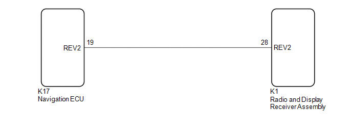
WIRING DIAGRAM
PROCEDURE
| 1. |
CHECK HARNESS AND CONNECTOR (RADIO AND DISPLAY RECEIVER ASSEMBLY - NAVIGATION ECU) |
(a) Disconnect the K1 radio and display receiver assembly connector.
(b) Disconnect the K17 navigation ECU connector.
(c) Measure the resistance according to the value(s) in the table below.
Standard Resistance:
|
Tester Connection | Condition |
Specified Condition |
|---|---|---|
|
K1-28 (REV2) - K17-19 (REV2) |
Always | Below 1 Ω |
|
K1-28 (REV2) or K17-19 (REV2) - Body ground |
Always | 10 kΩ or higher |
| OK | .gif) | PROCEED TO NEXT SUSPECTED AREA SHOWN IN PROBLEM SYMPTOMS TABLE
|
.gif)
| NG | | REPAIR OR REPLACE HARNESS OR CONNECTOR |
READ NEXT:
 Start Up Signal Circuit between Radio Receiver Assembly and Navigation ECU
DESCRIPTION This circuit includes the navigation ECU and radio and display receiver assembly. WIRING DIAGRAM
PROCEDURE
1.
CHECK HARNESS AND CONNECTOR (RADIO AND DISPLAY RECEIVER ASSEMBLY
Voice Guidance Circuit between Radio Receiver and Stereo Component Amplifier
DESCRIPTION Using this circuit, the radio and display receiver assembly sends signals to the stereo component amplifier assembly. WIRING DIAGRAM
PROCEDURE
1.
CHECK HARNESS AND CONNECTOR
Microphone Circuit
DESCRIPTION
w/o Manual (SOS) Switch:
The radio and display receiver assembly, roof console box sub-assembly and telephone microphone assembly are connected to each other using the microphone co
SEE MORE:
Problem Symptoms Table
PROBLEM SYMPTOMS TABLE HINT: Use the table below to help determine the cause of problem symptoms. If multiple suspected areas are listed, the potential causes of the symptoms are listed in order of probability in the "Suspected Area" column of the table. Check each symptom by checking the suspected
Emergency flashers
The emergency flashers are used to warn other drivers when the
vehicle has to be stopped on the road due to a breakdown, etc.
Press the switch.
All the turn signal lights will flash.
To turn them off, press the switch
once again.
■Emergency flashers
If the emergency flashers are us
© 2023-2025 Copyright www.tocamry.com
