Toyota Camry (XV70): Removal
REMOVAL
CAUTION / NOTICE / HINT
The necessary procedures (adjustment, calibration, initialization, or registration) that must be performed after parts are removed, installed, or replaced during the battery removal/installation are shown below.
Necessary Procedure After Parts Removed/Installed/Replaced|
Replacement Part or Procedure |
Necessary Procedures | Effects / Inoperative when not performed |
Link |
|---|---|---|---|
|
Battery terminal is disconnected/reconnected |
Perform steering sensor zero point calibration |
Lane Tracing Assist System |
|
|
Pre-collision System | |||
|
Memorize steering angle neutral point |
Parking assist monitor system |
| |
|
Panoramic view monitor system |
|
PROCEDURE
1. PRECAUTION
NOTICE:
- After turning the ignition switch off, waiting time may be required before disconnecting the cable from the negative (-) battery terminal. Therefore, make sure to read the disconnecting the cable from the negative (-) battery terminal notices before proceeding with work.
Click here
.gif)
- When replacing the battery, use a new battery of the same dimensions with a capacity of 60 Ah or more at a 20-hour rate.
2. DISCONNECT CABLE FROM NEGATIVE BATTERY TERMINAL
| (a) Loosen the nut, and disconnect the cable from the negative (-) battery terminal. NOTICE: When disconnecting the cable, some systems need to be initialized after the cable is reconnected. Click here |
|
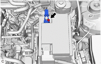
3. REMOVE BATTERY
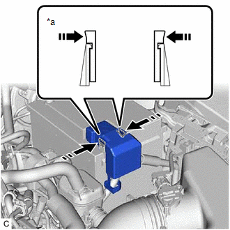
(a) Disengage the 2 claws and remove the battery terminal cap from the positive (+) battery terminal in the order shown in the illustration.
|
*a | Side View of Claws |
.png) |
Push Battery Terminal Cap Here |
.png) |
Push |
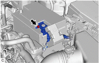
| (b) Loosen the nut and disconnect the cable from the positive (+) battery terminal. |
|
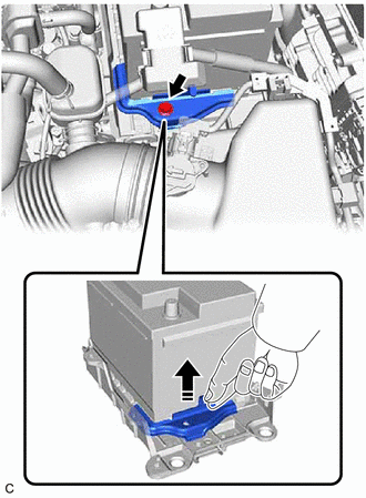
(c) Remove the bolt and No. 2 battery clamp from the battery clamp sub-assembly.
|
|
Remove in this Direction |
(d) Remove the battery from the vehicle.
READ NEXT:
 Installation
INSTALLATION PROCEDURE 1. INSTALL BATTERY
(a) Install the battery to the vehicle. (b) Install the No. 2 battery clamp with the bolt to the battery clamp sub-assembly.
Torque: 18.5 N
Components
COMPONENTS ILLUSTRATION
*1 RADIATOR CAP SUB-ASSEMBLY
*2 RADIATOR DRAIN COCK PLUG
*3 NO. 1 ENGINE UNDER COVER
- -
SEE MORE:
O2 Sensor Slow Response - Rich to Lean Bank 1 Sensor 1 (P014C00-P014F00,P015A00-P015D00)
DESCRIPTION Refer to DTC P219519. Click here
HINT: Although the DTC titles say oxygen sensor, these DTCs relate to the air fuel ratio sensor.
DTC No. Detection Item
DTC Detection Condition Trouble Area
MIL Memory
Note P014C00
O2 Sensor Slow Response - Rich to
Reverse Signal Circuit
DESCRIPTION The radio and display receiver assembly receives a reverse signal from the BKUP LP relay. WIRING DIAGRAM
PROCEDURE
1.
CHECK BACK-UP LIGHT (a) Move the shift lever to R and check if the back-up lights come on.
OK: The back-up lights come on.
NG
GO TO LIGHTIN
