Toyota Camry (XV70): Removal
REMOVAL
CAUTION / NOTICE / HINT
NOTICE:
- Immediately after installing the brake pads, the braking performance may be reduced. Always perform a road test in a safe place while paying attention to the surroundings.
- After replacing the rear disc brake pads, the brake pedal may feel soft due to clearance between the rear disc brake pads and rear disc. Depress the brake pedal several times until the brake pedal feels firm.
- After replacing the rear disc brake pads, always perform a road test to check the braking performance and check for vibrations.
HINT:
- Use the same procedure for the RH side and LH side.
- The following procedure is for the LH side.
PROCEDURE
1. REMOVE REAR WHEEL
Click here .gif)
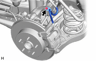
2. SEPARATE REAR FLEXIBLE HOSE
| (a) Remove the bolt and separate the rear flexible hose from the rear flexible hose bracket. |
|
3. REMOVE REAR DISC BRAKE PAD
CAUTION:
- Be careful not to get pinched by the rear disc brake cylinder assembly or other parts when removing the rear disc brake pads.
- After lifting up the rear disc brake cylinder assembly, secure it in place before performing any work on it.
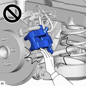
- The rear disc brake cylinder assembly could fall, pinching hands or fingers and causing injury.
| (a) Hold the rear disc brake cylinder slide pin (lower side) and remove the bolt. |
|
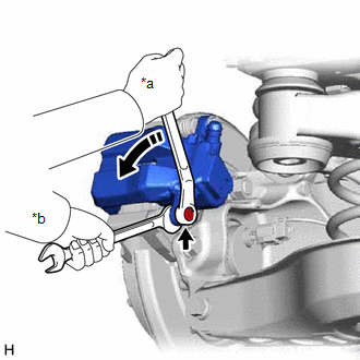
(b) Pull the rear disc brake cylinder assembly upward.
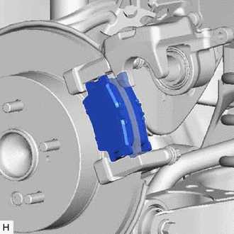
| (c) Remove the 2 rear disc brake pads from the rear disc brake cylinder mounting. |
|
4. REMOVE REAR DISC BRAKE ANTI-SQUEAL SHIM KIT
(a) Remove the rear No. 1 disc brake anti-squeal shim from each rear disc brake pad.
| (b) Using a screwdriver, remove the rear disc brake pad wear indicator plate from each rear disc brake pad. |
|
.png)
READ NEXT:
 Installation
INSTALLATION CAUTION / NOTICE / HINT
NOTICE:
Immediately after installing the brake pads, the braking performance may be reduced. Always perform a road test in a safe place while paying attentio
Rear Side Marker Light Bulb
ComponentsCOMPONENTS ILLUSTRATION
*1 REAR COMBINATION LIGHT ASSEMBLY
*2 REAR COMBINATION LIGHT COVER
*3 REAR SIDE MARKER LIGHT BULB
- - RemovalREMOVAL CAUTION
Rear Turn Signal Light Bulb
ComponentsCOMPONENTS ILLUSTRATION
*1 REAR COMBINATION LIGHT ASSEMBLY
*2 REAR COMBINATION LIGHT COVER
*3 REAR TURN SIGNAL LIGHT BULB
- - RemovalREMOVAL CAUTION
SEE MORE:
Acn Call End
ACN CALL END ACN CALL END This function terminates the ACN (Automatic Collision Notification) to the telematics provider. After a collision in which the DCM receives "Collision Detection Signal", the vehicle will send the emergency call notification to the telematics provider until the emergency cal
Installation
INSTALLATION PROCEDURE 1. TEMPORARILY INSTALL FUEL (ENGINE ROOM SIDE) PUMP ASSEMBLY
(a) Turn the crankshaft pulley until the flat of the camshaft faces the fuel pump lifter assembly.
HINT: This prevents the camshaft nose from pushing up the fuel pump lifter assembly when installing the fuel
© 2023-2025 Copyright www.tocamry.com
