Toyota Camry (XV70): Removal
REMOVAL
CAUTION / NOTICE / HINT
HINT:
- Use the same procedure for the RH side and LH side.
- The following procedure is for the LH side.
PROCEDURE
1. PRECAUTION
Click here
.gif)
2. RELEASE PARKING BRAKE
(a) Move the shift lever to P.
(b) Turn the engine switch on (IG).
(c) Operate the electric parking brake switch assembly to release the parking brake.
HINT:
If the parking brake cannot be released:
Click here
(d) Turn the engine switch off.
3. REMOVE REAR WHEEL
Click here
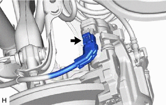
4. DISCONNECT NO. 2 PARKING BRAKE WIRE ASSEMBLY
| (a) Disconnect the No. 2 parking brake wire assembly connector from the parking brake actuator assembly. NOTICE:
|
|
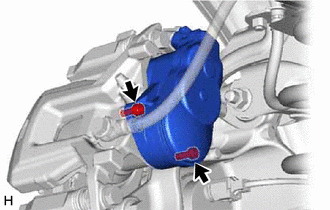
5. REMOVE PARKING BRAKE ACTUATOR ASSEMBLY
| (a) Using a 5 mm hexagon socket wrench, remove the 2 bolts and parking brake actuator assembly from the rear disc brake cylinder assembly. NOTICE:
|
|
(b) Remove the O-ring from the rear disc brake cylinder assembly.
READ NEXT:
 Inspection
INSPECTION PROCEDURE 1. INSPECT PARKING BRAKE ACTUATOR ASSEMBLY
(a) Parking brake actuator assembly operation inspection
(1) Apply voltage to the terminals of the parking brake actuator assemb
Installation
INSTALLATION CAUTION / NOTICE / HINT
HINT:
Use the same procedure for the RH side and LH side.
The following procedure is for the LH side.
PROCEDURE 1. INSTALL PARKING BRAKE ACTUATOR ASS
Electric Parking Brake Switch
ComponentsCOMPONENTS ILLUSTRATION
*1 ELECTRIC PARKING BRAKE SWITCH ASSEMBLY
- - RemovalREMOVAL PROCEDURE
1. PRECAUTION Click here
2. REMOVE REAR UPPER CONSOLE PANEL SUB-AS
SEE MORE:
Right Front Wheel Speed Sensor Circuit Short to Ground or Open (C050614)
DESCRIPTION Refer to DTC C050612 Click here
DTC No. Detection Item
DTC Detection Condition Trouble Area
C050614 Right Front Wheel Speed Sensor Circuit Short to Ground or Open
A short or open circuit is detected in the speed sensor signal circuit for 0.12 seconds or
Multi-axis Acceleration Sensor Module "A" Signal Stuck In Range (C05202A)
DESCRIPTION The airbag sensor assembly has a built-in yaw rate and acceleration sensor and detects the vehicle condition.
The skid control ECU (brake actuator assembly) memorizes the range of the acceleration sensor (airbag sensor assembly) and the range of vehicle speed calculated using each spee
