Toyota Camry (XV70): Electric Parking Brake Switch
Components
COMPONENTS
ILLUSTRATION
|
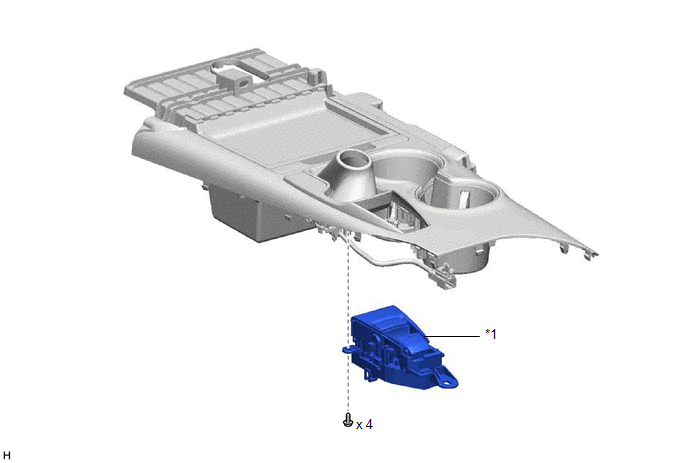
*1 | ELECTRIC PARKING BRAKE SWITCH ASSEMBLY |
- | - |
Removal
REMOVAL
PROCEDURE
1. PRECAUTION
Click here .gif)
2. REMOVE REAR UPPER CONSOLE PANEL SUB-ASSEMBLY
Click here
3. REMOVE ELECTRIC PARKING BRAKE SWITCH ASSEMBLY
| (a) Disengage the clamp and guide. |
|
.png)
(b) Remove the 4 screws and electric parking brake switch assembly.
Inspection
INSPECTION
PROCEDURE
1. INSPECT ELECTRIC PARKING BRAKE SWITCH ASSEMBLY
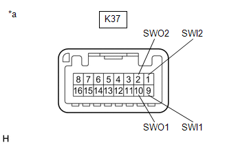
(a) Check the resistance.
| (1) Measure the resistance according to the value(s) in the table below. Standard Resistance:
If the result is not as specified, replace the electric parking brake switch assembly. |
|
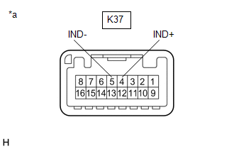
(b) Check the Illuminates.
| (1) Apply battery voltage to the electric parking brake switch assembly and check that the switch illuminates. OK:
If the result is not as specified, replace the electric parking brake switch assembly. |
|
Installation
INSTALLATION
PROCEDURE
1. INSTALL ELECTRIC PARKING BRAKE SWITCH ASSEMBLY
(a) Install the electric parking brake switch assembly with the 4 screws.
(b) Engage the guide and clamp.
2. INSTALL REAR UPPER CONSOLE PANEL SUB-ASSEMBLY
Click here .gif)
READ NEXT:
 Precaution
PRECAUTION PRECAUTION FOR DISCONNECTING CABLE FROM NEGATIVE BATTERY TERMINAL
NOTICE: When disconnecting the cable from the negative (-) battery terminal, initialize the following system(s) after the
Parts Location
PARTS LOCATION ILLUSTRATION
*1 BRAKE ACTUATOR ASSEMBLY
- SKID CONTROL ECU *2
ECM *3
ENGINE ROOM RELAY BLOCK AND JUNCTION BLOCK ASSEMBLY - ABS NO. 2 FUSE
- -
SEE MORE:
Components
COMPONENTS ILLUSTRATION
*A for 2WD
*B for AWD
*1 IGNITION COIL ASSEMBLY
*2 NO. 1 ENGINE COVER SUB-ASSEMBLY
*3 SPARK PLUG
- -
N*m (kgf*cm, ft.*lbf): Specified torque
- -
Precaution
PRECAUTION BASIC REPAIR HINT (a) HINTS ON OPERATIONS
1 Attire
Always wear a clean uniform.
A hat and safety shoes must be worn.
2
Vehicle protection Prepare a grille cover, fender cover, seat cover and floor mat before starting work.
3 Safety proce
