Toyota Camry (XV70): Parts Location
Toyota Camry Repair Manual XV70 (2018-2024) / Brake / Parking Brake / Electric Parking Brake System / Parts Location
PARTS LOCATION
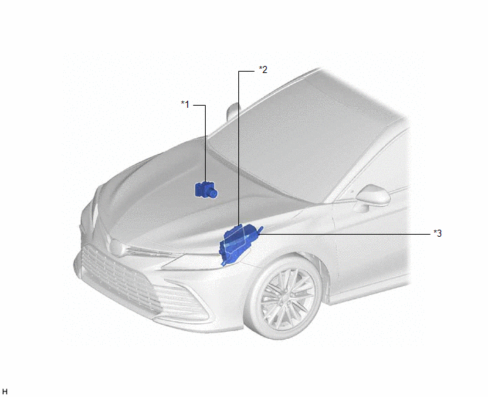
ILLUSTRATION
|
*1 | BRAKE ACTUATOR ASSEMBLY - SKID CONTROL ECU | *2 |
ECM |
| *3 |
ENGINE ROOM RELAY BLOCK AND JUNCTION BLOCK ASSEMBLY - ABS NO. 2 FUSE |
- | - |
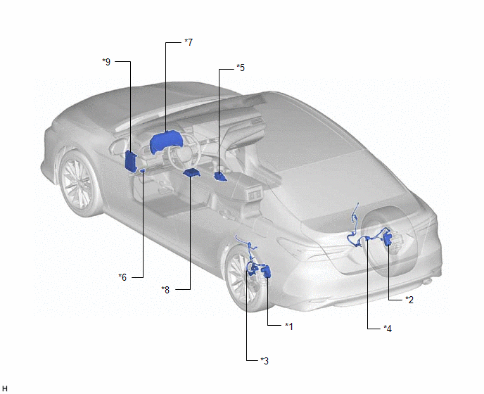
ILLUSTRATION
|
*1 | PARKING BRAKE ACTUATOR ASSEMBLY LH |
*2 | PARKING BRAKE ACTUATOR ASSEMBLY RH |
|
*3 | NO. 2 PARKING BRAKE WIRE ASSEMBLY |
*4 | NO. 1 PARKING BRAKE WIRE ASSEMBLY |
|
*5 | ELECTRIC PARKING BRAKE SWITCH ASSEMBLY |
*6 | DLC3 |
|
*7 | COMBINATION METER ASSEMBLY |
*8 | ACCELERATION SENSOR (AIRBAG SENSOR ASSEMBLY) |
|
*9 | INSTRUMENT PANEL JUNCTION BLOCK ASSEMBLY - ECU-IG1 NO. 2 FUSE - ECU-B NO. 2 FUSE |
- | - |
READ NEXT:
 System Diagram
SYSTEM DIAGRAM
How To Proceed With Troubleshooting
CAUTION / NOTICE / HINT HINT: *: Use the Techstream. PROCEDURE
1.
VEHICLE BROUGHT TO WORKSHOP
NEXT
2.
CUSTOMER PROBLEM ANALYSIS (a) Interview
Problem Symptoms Table
PROBLEM SYMPTOMS TABLE
HINT:
Use the table below to help determine the cause of problem symptoms. If multiple suspected areas are listed, the potential causes of the symptoms are listed in order
SEE MORE:
Parking Brake Switch Circuit
DESCRIPTION This circuit is from the parking brake switch assembly*1 or skid control ECU (Brake Actuator Assembly)*2 to the radio and display receiver assembly.
*1: w/o Electric Parking Brake System
*2: w/ Electric Parking Brake System
WIRING DIAGRAM w/o Electric Parking Brake System
w/
Installation
INSTALLATION PROCEDURE 1. INSTALL HEATED OXYGEN SENSOR (for Bank 2)
HINT: Perform "Inspection After Repair" after replacing the heated oxygen sensor.
Click here
(a) Using SST, install the heated oxygen sensor to the front exhaust pipe assembly.
SST: 09224-00012 Torque: Specified
© 2023-2025 Copyright www.tocamry.com
