Toyota Camry (XV70): Removal
REMOVAL
CAUTION / NOTICE / HINT
HINT:
- Use the same procedure for the RH side and LH side.
- The following procedure is for the LH side.
PROCEDURE
1. REMOVE REAR WHEEL
Click here
.gif)
2. DISCONNECT NO. 2 PARKING BRAKE WIRE ASSEMBLY
| (a) Disconnect the No. 2 parking brake wire assembly connector from the parking brake actuator assembly. NOTICE:
|
|
.png)
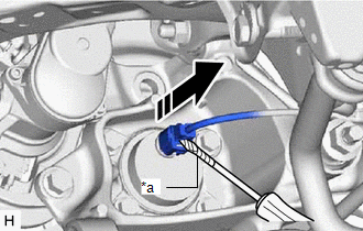
| (b) Using a screwdriver with its tip wrapped with protective tape, disconnect the No. 2 parking brake wire assembly connector from the rear axle hub and bearing assembly. NOTICE: Be careful not to damage the rear axle hub and bearing assembly or connector cover. |
|
3. SEPARATE REAR DISC BRAKE CALIPER ASSEMBLY
Click here
4. REMOVE REAR DISC
Click here
5. REMOVE REAR AXLE HUB AND BEARING ASSEMBLY
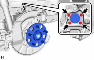
| (a) Remove the 4 bolts, rear axle hub and bearing assembly and rear disc brake dust cover sub-assembly from the rear axle carrier sub-assembly. |
|
READ NEXT:
 Installation
INSTALLATION CAUTION / NOTICE / HINT
HINT:
Use the same procedure for the RH side and LH side.
The following procedure is for the LH side.
PROCEDURE 1. INSTALL REAR AXLE HUB AND BEARING
Components
COMPONENTS ILLUSTRATION
*1 PARKING BRAKE SHOE ADJUSTING HOLE PLUG
*2 REAR AXLE HUB AND BEARING ASSEMBLY
*3 REAR DISC
*4 REAR DISC BRAKE CALIPER ASSEMBLY
*
SEE MORE:
Data List / Active Test
DATA LIST / ACTIVE TEST DATA LIST NOTICE:
In the table below, the values listed under "Normal Condition" are reference values. Do not depend solely on these reference values when deciding whether a part is faulty or not.
HINT: Using the Techstream to read the Data List allows the values or state
Mute Signal Circuit between Stereo Component Amplifier and Telematics Transceiver
DESCRIPTION The DCM (telematics transceiver) sends a mute signal to the stereo component amplifier assembly.
The stereo component amplifier assembly controls the volume according to the mute signal from the DCM (telematics transceiver). WIRING DIAGRAM
CAUTION / NOTICE / HINT
NOTICE:
Depen
