Toyota Camry (XV70): Removal
REMOVAL
CAUTION / NOTICE / HINT
HINT:
- Use the same procedure for the RH side and LH side.
- The following procedure is for the LH side.
PROCEDURE
1. REMOVE REAR WHEEL
Click here
.gif)
2. REMOVE REAR AXLE SHAFT NUT
| (a) Using SST and a hammer, release the staked part of the rear axle shaft nut. SST: 09930-00010 NOTICE: Loosen the staked part of the rear axle shaft nut completely, otherwise the threads of the rear drive shaft assembly may be damaged. |
|
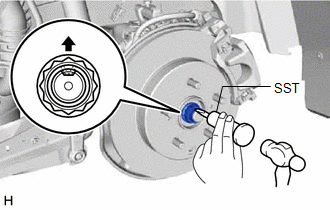
(b) While applying the brakes, using a 30 mm deep socket wrench, remove the rear axle shaft nut.
3. DISCONNECT NO. 2 PARKING BRAKE WIRE ASSEMBLY
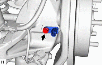
| (a) Disconnect the No. 2 parking brake wire assembly connector from the parking brake actuator assembly. NOTICE:
|
|
.png)
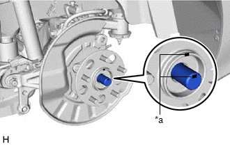
| (b) Using a screwdriver with its tip wrapped with protective tape, disconnect the No. 2 parking brake wire assembly connector from the rear skid control sensor. NOTICE:
|
|
.png)
4. REMOVE REAR SKID CONTROL SENSOR
| (a) Remove the bolt and the rear skid control sensor from the rear axle carrier sub-assembly. NOTICE:
|
|
5. SEPARATE REAR DISC BRAKE CALIPER ASSEMBLY
Click here
6. REMOVE REAR DISC
Click here
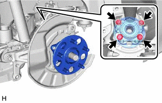
7. REMOVE REAR AXLE HUB AND BEARING ASSEMBLY
| (a) Put matchmarks on the rear drive shaft assembly and rear axle hub and bearing assembly. |
|
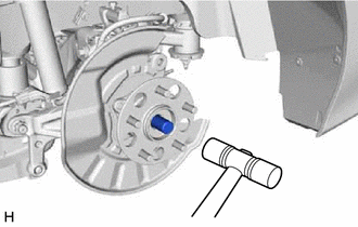
| (b) Using a plastic hammer, separate the rear drive shaft assembly from the rear axle hub and bearing assembly. HINT: If it is difficult to separate the rear drive shaft assembly from the rear axle hub and bearing assembly, tap the end of the rear drive shaft assembly using a brass bar and a hammer. |
|
| (c) Remove the 4 bolts, rear axle hub and bearing assembly and rear disc brake dust cover sub-assembly from the rear axle carrier sub-assembly. |
|
READ NEXT:
 Installation
INSTALLATION CAUTION / NOTICE / HINT
HINT:
Use the same procedure for the RH side and LH side.
The following procedure is for the LH side.
PROCEDURE 1. INSTALL REAR AXLE HUB AND BEARING
Rear Axle Hub Bolt(w/ Electric Parking Brake System)
ComponentsCOMPONENTS ILLUSTRATION
*1 NO. 2 PARKING BRAKE WIRE ASSEMBLY
*2 REAR AXLE HUB BOLT
*3 REAR DISC
*4 REAR DISC BRAKE CALIPER ASSEMBLY
*5 REAR FL
Rear Axle Hub Bolt(w/o Electric Parking Brake System)
ComponentsCOMPONENTS ILLUSTRATION
*1 PARKING BRAKE SHOE ADJUSTING HOLE PLUG
*2 REAR AXLE HUB BOLT
*3 REAR DISC
*4 REAR DISC BRAKE CALIPER ASSEMBLY
*5 RE
SEE MORE:
Startability Malfunction (P160400)
DESCRIPTION This DTC is stored when the engine does not start even though the STA signal is input or when the engine takes a long time to start, and when the engine speed is low or the engine stalls just after the engine starts.
Using the Techstream, the conditions present when the DTC was stored
Evaporative Emission System Leak Detected (Large Leak) (P045500,P045600)
DTC SUMMARY
DTC No. Detection Item
DTC Detection Condition Trouble Area
MIL Memory
Note P045500
Evaporative Emission System Leak Detected (Large Leak)
Leak detection pump creates negative pressure (vacuum) in EVAP system and EVAP system pressure is measured
