Toyota Camry (XV70): Removal
REMOVAL
CAUTION / NOTICE / HINT
The necessary procedures (adjustment, calibration, initialization, or registration) that must be performed after parts are removed and installed, or replaced during front drive shaft assembly removal/installation are shown below.
Necessary Procedures After Parts Removed/Installed/Replaced|
Replaced Part or Performed Procedure |
Necessary Procedure | Effect/Inoperative Function when Necessary Procedure not Performed |
Link |
|---|---|---|---|
| Front wheel alignment adjustment |
|
|
|
|
Automatic transaxle fluid |
ATF thermal degradation estimate reset |
The value of the Data List item "ATF Thermal Degradation Estimate" is not estimated correctly. |
|
HINT:
- Use the same procedure for the RH side and LH side.
- The following procedure is for the LH side.
PROCEDURE
1. REMOVE FRONT WHEELS
Click here
.gif)
2. REMOVE FRONT WHEEL OPENING EXTENSION PAD LH
Click here
3. REMOVE FRONT WHEEL OPENING EXTENSION PAD RH
Click here
4. REMOVE NO. 1 ENGINE UNDER COVER
Click here
5. REMOVE REAR ENGINE UNDER COVER LH
Click here
6. REMOVE REAR ENGINE UNDER COVER RH
Click here
7. REMOVE FRONT FENDER APRON SEAL LH
Click here
8. REMOVE FRONT FENDER APRON SEAL RH
Click here
9. DRAIN AUTOMATIC TRANSAXLE FLUID
Click here
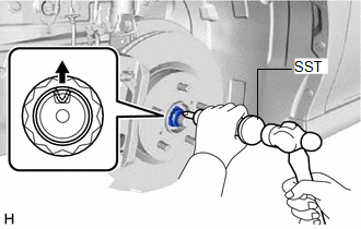
10. REMOVE FRONT AXLE SHAFT NUT
| (a) Using SST and a hammer, release the staked part of the front axle shaft nut. SST: 09930-00010 NOTICE: Fully loosen the staked part of the front axle shaft nut, otherwise the threads of the drive shaft may be damaged. |
|
(b) While applying the brakes, remove the front axle shaft nut.
11. SEPARATE FRONT SPEED SENSOR
Click here
12. SEPARATE TIE ROD ASSEMBLY
Click here
13. SEPARATE FRONT STABILIZER LINK ASSEMBLY
Click here
14. SEPARATE FRONT LOWER NO. 1 SUSPENSION ARM SUB-ASSEMBLY
Click here
15. SEPARATE FRONT DRIVE SHAFT ASSEMBLY
Click here
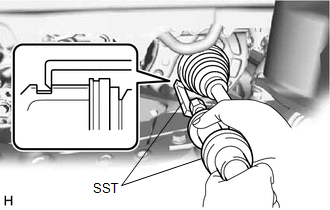
16. REMOVE FRONT DRIVE SHAFT ASSEMBLY LH
| (a) Using SST, remove the front drive shaft assembly LH. SST: 09520-01010 SST: 09520-24010 09520-32040 NOTICE:
|
|
17. REMOVE FRONT DRIVE SHAFT ASSEMBLY RH
| (a) Remove the 2 bolts and pull out the drive shaft together with the drive shaft bearing case sub-assembly. |
|
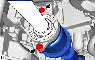
(b) Remove the front drive shaft assembly RH from the drive shaft bearing bracket.
NOTICE:
- Do not damage the front drive shaft oil seal RH.
- Do not damage the front axle inboard joint boot.
- Do not drop the front drive shaft assembly RH.
HINT:
If it is difficult to disengage the fitting, tap the end of the front drive inboard joint assembly with a brass bar and a hammer.
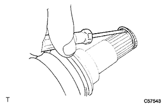
18. REMOVE FRONT DRIVE SHAFT HOLE SNAP RING
| (a) Using a screwdriver, remove the front drive shaft hole snap ring. |
|
READ NEXT:
 Disassembly
DISASSEMBLY CAUTION / NOTICE / HINT
HINT:
Use the same procedure for the RH side and LH side.
The following procedure is for the LH side.
PROCEDURE 1. SEPARATE FRONT NO. 2 AXLE INBOARD J
Inspection
INSPECTION PROCEDURE 1. INSPECT FRONT DRIVE SHAFT ASSEMBLY
(a) Check that there is no excessive play in the radial direction of the outboard joint.
(b) Check that the inboar
Reassembly
REASSEMBLY CAUTION / NOTICE / HINT
HINT:
Use the same procedure for the RH side and LH side.
The following procedure is for the LH side.
PROCEDURE 1. INSTALL FRONT AXLE OUTBOARD JOINT BO
SEE MORE:
On-vehicle Inspection
ON-VEHICLE INSPECTION PROCEDURE
1. INSPECT GARAGE DOOR OPENER
(a) Press each garage door opener ("HomeLink") switch and check that the ("HomeLink") indicator light turns on. If one or more of the garage door opener ("HomeLink") switches does not turn on the ("HomeLink") indicator light, chec
Taking out the spare tire
1. Lift up the hook of the luggage
floor cover on the trunk floor.
2. Secure the luggage floor cover
using the hook provided.
3. Remove the tool tray.
2WD models
AWD models
4. Loosen the center fastener that
secures the spare tire.
When taking out or stowing the
spare tire, make
