Toyota Camry (XV70): Removal
REMOVAL
CAUTION / NOTICE / HINT
The necessary procedures (adjustment, calibration, initialization, or registration) that must be performed after parts are removed and installed, or replaced during front drive shaft assembly removal/installation are shown below.
Necessary Procedures After Parts Removed/Installed/Replaced|
Replaced Part or Performed Procedure |
Necessary Procedure | Effect/Inoperative Function when Necessary Procedure not Performed |
Link |
|---|---|---|---|
| Front wheel alignment adjustment |
|
| w/ Electric Parking Brake System: w/o Electric Parking Brake System: |
|
Automatic transaxle fluid |
ATF thermal degradation estimate reset |
The value of the Data List item "ATF Thermal Degradation Estimate" is not estimated correctly. |
|
HINT:
- Use the same procedure for the RH side and LH side.
- The following procedure is for the LH side.
PROCEDURE
1. REMOVE FRONT WHEELS
Click here
.gif)
2. REMOVE FRONT WHEEL OPENING EXTENSION PAD RH
Click here
3. REMOVE FRONT WHEEL OPENING EXTENSION PAD LH
Click here
4. REMOVE NO. 1 ENGINE UNDER COVER
Click here
5. REMOVE NO. 2 ENGINE UNDER COVER ASSEMBLY
Click here
6. REMOVE FRONT FENDER APRON SEAL LH
Click here
7. REMOVE FRONT FENDER APRON SEAL RH
Click here
8. DRAIN AUTOMATIC TRANSAXLE FLUID
for UB80E: Click here
for UB80F: Click here
9. DRAIN TRANSFER OIL (for AWD)
Click here
10. REMOVE FRONT AXLE SHAFT NUT
| (a) Using SST and a hammer, release the staked part of the front axle shaft nut. SST: 09930-00010 NOTICE: Fully loosen the staked part of the front axle shaft nut, otherwise the threads of the drive shaft may be damaged. |
|
.png)
(b) While applying the brakes, remove the front axle shaft nut.
11. SEPARATE FRONT SPEED SENSOR
Click here
12. SEPARATE TIE ROD ASSEMBLY
Click here
13. SEPARATE FRONT STABILIZER LINK ASSEMBLY
Click here
14. SEPARATE FRONT LOWER NO. 1 SUSPENSION ARM SUB-ASSEMBLY
Click here
15. SEPARATE FRONT DRIVE SHAFT ASSEMBLY
Click here
16. REMOVE FRONT DRIVE SHAFT ASSEMBLY LH
| (a) Using SST, remove the front drive shaft assembly LH. SST: 09520-01011 SST: 09520-20010 09521-02010 09521-02040 09521-02060 NOTICE:
|
|
.png)
17. REMOVE FRONT DRIVE SHAFT ASSEMBLY RH (for 2WD)
| (a) Remove the 2 bolts and pull out the drive shaft together with the drive shaft bearing case sub-assembly. |
|
(b) Remove the front drive shaft assembly RH from the drive shaft bearing bracket.
NOTICE:
- Do not damage the front drive shaft oil seal RH.
- Do not damage the front axle inboard joint boot.
- Do not drop the front drive shaft assembly RH.
HINT:
If it is difficult to disengage the fitting, tap the end of the front drive inboard joint assembly with a brass bar and a hammer.
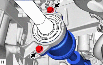
18. REMOVE FRONT DRIVE SHAFT ASSEMBLY RH (for AWD)
| (a) Separate the drive shaft bearing bracket hole snap ring from the drive shaft bearing bracket. |
|
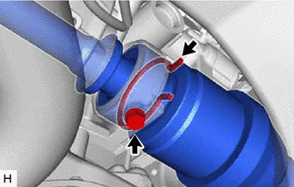
(b) Remove the No. 1 drive shaft bearing bracket setting bolt and front drive shaft assembly RH from the transfer assembly.
NOTICE:
- Do not damage the transfer case oil seal RH.
- Do not damage the front axle inboard joint boot.
- Do not drop the front drive shaft assembly RH.
HINT:
If it is difficult to disengage the fitting, tap the end of the front drive inboard joint assembly with a brass bar and a hammer.
(c) Remove the drive shaft bearing bracket hole snap ring from the front drive shaft assembly RH.
19. REMOVE FRONT DRIVE SHAFT HOLE SNAP RING
| (a) Using a screwdriver, remove the front drive shaft hole snap ring. |
|
.png)
READ NEXT:
 Disassembly
DISASSEMBLY CAUTION / NOTICE / HINT
HINT:
Use the same procedure for the RH side and LH side.
The following procedure is for the LH side.
PROCEDURE 1. SEPARATE FRONT NO. 2 AXLE INBOARD J
Inspection
INSPECTION PROCEDURE 1. INSPECT FRONT DRIVE SHAFT ASSEMBLY
(a) Check that there is no excessive play in the radial direction of the outboard joint.
(b) Check that the inboar
Reassembly
REASSEMBLY CAUTION / NOTICE / HINT
HINT:
Use the same procedure for the RH side and LH side.
The following procedure is for the LH side.
PROCEDURE 1. INSTALL FRONT DRIVE SHAFT BEARING (f
SEE MORE:
Transmission Fluid Temperature Sensor "A" Circuit Short to Battery or Open (P071015)
DESCRIPTION The ATF temperature sensor converts the automatic transaxle fluid (ATF) temperature into a resistance value for use by the ECM.
The ECM applies voltage to the temperature sensor through terminal THO1 of the ECM.
The sensor resistance changes with the ATF temperature. As the temperatu
Tire pressure warning system
Your vehicle is equipped with a tire pressure warning system that uses
tire pressure warning valve and transmitters to detect low tire inflation
pressure before serious problems arise.
Vehicles without a tire inflation pressure display function
If the tire pressure drops below a predetermined le
