Toyota Camry (XV70): Removal
REMOVAL
PROCEDURE
1. REMOVE FRONT WHEEL RH
Click here .gif)
2. REMOVE FRONT FENDER APRON SEAL RH
Click here
3. REMOVE V-BANK COVER SUB-ASSEMBLY
Click here
4. REMOVE CAMSHAFT TIMING OIL CONTROL SOLENOID ASSEMBLY (for Exhaust Side of Bank 1)
Click here
5. SET NO. 1 CYLINDER TO TDC/COMPRESSION
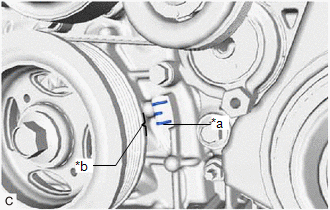
| (a) Turn the crankshaft pulley clockwise until its timing mark (cutout) is aligned with the timing mark on the timing chain cover assembly as shown in the illustration. |
|
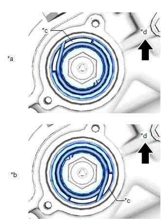
| (b) Check that the cutout of the camshaft timing gear assembly is at the top. HINT: If the cutout of the camshaft timing gear assembly is not at the top, turn the crankshaft 360° clockwise and align the timing mark (cutout) of the crankshaft pulley with the timing mark on the timing chain cover assembly again. |
|
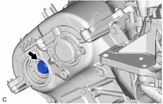
6. REMOVE CAMSHAFT TIMING GEAR BOLT
| (a) While holding the crankshaft pulley, remove the camshaft timing gear bolt. NOTICE:
|
|
READ NEXT:
 Inspection
INSPECTION PROCEDURE 1. INSPECT CAMSHAFT TIMING GEAR BOLT
(a) Check the stroke of the plunger in the center of the camshaft timing gear bolt.
Standard Stroke: 2.2 mm (0.0866 in.) or more HIN
Installation
INSTALLATION PROCEDURE 1. INSTALL CAMSHAFT TIMING GEAR BOLT
(a) Make sure that the No. 1 cylinder is at TDC/compression. HINT:
Check that the cutout of the camshaft timing gear assembly is at the
SEE MORE:
Right Front Wheel Speed Sensor Circuit Short to Battery (C050612)
DESCRIPTION Each speed sensor detects wheel speed and sends signals to the skid control ECU (brake actuator assembly). These signals are used by the ABS control.
The speed sensor detects the magnetic fields of the speed sensor rotor as it rotates and outputs a pulse signal.
The frequency of the
Parts Location
PARTS LOCATION ILLUSTRATION
*1 FRONT NO. 2 SPEAKER ASSEMBLY RH
*2 NAVIGATION ANTENNA ASSEMBLY
- Telephone Sub
*3 RADIO AND DISPLAY RECEIVER ASSEMBLY
*4 DCM (TELEMATICS TRANSCEIVER)
*5 NAVIGATION ECU (w/ Navigation System)
*6 DLC3 ILLUSTRA
