Toyota Camry (XV70): Removal
REMOVAL
CAUTION / NOTICE / HINT
The necessary procedures (adjustment, calibration, initialization, or registration) that must be performed after parts are removed and installed, or replaced during camshaft removal/installation are shown below.
Necessary Procedure After Parts Removed/Installed/Replaced|
Replaced Part or Performed Procedure |
Necessary Procedure | Effect/Inoperative Function when Necessary Procedure not Performed |
Link |
|---|---|---|---|
| *1: When the ECM is replaced with a new one, reset memory is unnecessary. | |||
| Battery terminal is disconnected/reconnected |
Perform steering sensor zero point calibration |
Lane Tracing Assist System |
|
|
Pre-collision System | |||
|
Memorize steering angle neutral point |
Parking Assist Monitor System |
| |
|
Panoramic view monitor system |
| ||
|
Replacement of ECM | Vehicle Identification Number (VIN) registration |
MIL comes on |
|
|
ECU communication ID registration (Immobiliser system) |
Engine start function |
| |
| Inspection After Repair |
|
|
|
Replacement of automatic transaxle assembly |
|
|
|
|
Replacement of ECM (If possible, read the transaxle compensation code from the previous ECM) |
| ||
| Replacement of ECM (If impossible, read the transaxle compensation code from the previous ECM) |
| ||
| Replacement of ECM |
Code registration |
|
|
|
Replacement of automatic transaxle fluid |
ATF thermal degradation estimate reset |
The value of the Data List item "ATF Thermal Degradation Estimate" is not estimated correctly. |
|
|
Suspension, tires, etc. (The vehicle height changes because of suspension or tire replacement) |
Rear television camera assembly optical axis (Back camera position setting) |
Parking assist monitor system |
|
|
Replacement of front bumper assembly |
Front television camera view adjustment |
Panoramic view monitor system |
|
|
Suspension, tires, etc. (The vehicle height changes because of suspension or tire replacement) |
| ||
| Front wheel alignment adjustment |
|
|
|
PROCEDURE
1. INSTALL ENGINE ASSEMBLY TO ENGINE STAND
Click here
.gif)
2. REMOVE ENGINE HANGERS
Click here
3. REMOVE THROTTLE BODY WITH MOTOR ASSEMBLY
Click here
4. DISCONNECT VENTILATION HOSE
Click here
5. DISCONNECT PURGE VALVE (PURGE VSV)
Click here
6. REMOVE NO. 2 SURGE TANK STAY
Click here
7. REMOVE INTAKE AIR SURGE TANK ASSEMBLY
Click here
8. REMOVE AIR SURGE TANK TO INTAKE MANIFOLD GASKET
Click here
9. REMOVE IGNITION COIL ASSEMBLY
Click here
10. REMOVE VACUUM PUMP ASSEMBLY
Click here
11. REMOVE ENGINE OIL LEVEL DIPSTICK GUIDE
Click here
12. REMOVE WIRE HARNESS CLAMP BRACKET
Click here
13. REMOVE WATER FILLER BRACKET
Click here
14. REMOVE CAMSHAFT TIMING OIL CONTROL SOLENOID ASSEMBLY (for Intake Side of Bank 1)
Click here
15. REMOVE CAMSHAFT TIMING OIL CONTROL SOLENOID ASSEMBLY (for Exhaust Side of Bank 1)
Click here
16. REMOVE CAMSHAFT TIMING OIL CONTROL SOLENOID ASSEMBLY (for Exhaust Side of Bank 2)
Click here
17. REMOVE CAMSHAFT TIMING OIL CONTROL SOLENOID ASSEMBLY (for Intake Side of Bank 2)
Click here
18. REMOVE VVT SENSOR (for Intake Side of Bank 1)
Click here
19. REMOVE VVT SENSOR (for Exhaust Side of Bank 1)
Click here
20. REMOVE VVT SENSOR (for Intake Side of Bank 2)
Click here
21. REMOVE VVT SENSOR (for Exhaust Side of Bank 2)
Click here
22. REMOVE CYLINDER HEAD COVER SUB-ASSEMBLY
Click here
23. REMOVE CYLINDER HEAD COVER SUB-ASSEMBLY LH
Click here
24. REMOVE SPARK PLUG TUBE GASKET
Click here
25. REMOVE TIMING CHAIN COVER PLATE
Click here
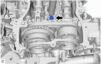
26. SET NO. 1 CYLINDER TO TDC (COMPRESSION)
| (a) Turn the crankshaft clockwise to align the timing mark (cutout) on the crankshaft pulley with the "0" timing mark on the timing chain cover assembly. |
|
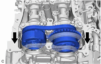
| (b) Check that the timing marks of the camshaft timing gear assemblies are aligned with the timing marks of the camshaft bearing caps as shown in the illustration. HINT: If the marks are not aligned, turn the crankshaft again to align the marks. |
|
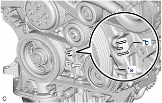
(c) Place paint marks on the timing marks and sprockets of each camshaft timing gear assembly and on the links of the chain sub-assembly.
HINT:
Be sure to place the paint marks on 2 links of the chain sub-assembly and on the sprockets of the camshaft timing gear assemblies at the locations of the timing marks of the camshaft timing gear assemblies.
27. REMOVE NO. 1 CHAIN TENSIONER ASSEMBLY
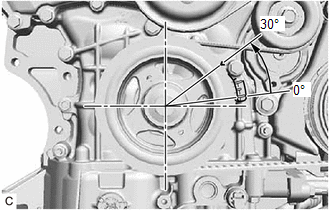
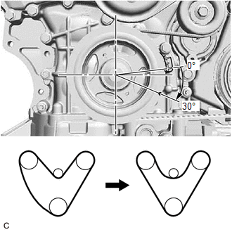
| (a) Turn the crankshaft approximately 30° counterclockwise so that there is some slack in the chain sub-assembly. HINT: This prevents the valves and pistons from interfering with each other. |
|
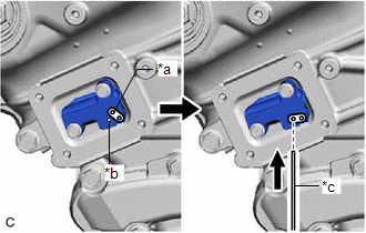
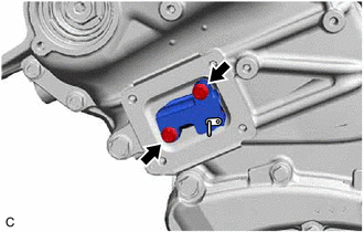
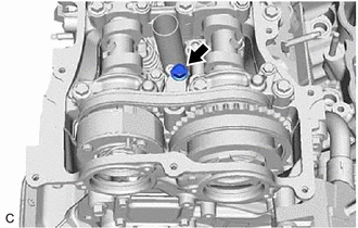
| (b) Align the hole in the lever of the No. 1 chain tensioner assembly with the hole in the tensioner body as shown in the illustration, and then insert a pin with a diameter of 1.0 mm (0.0394 in.) into the hole. NOTICE: Check that the pin is locked. |
|
| (c) Turn the crankshaft clockwise to align the timing mark (cutout) on the crankshaft pulley with the "0" timing mark on the timing chain cover assembly. |
|
| (d) Remove the 2 bolts and No. 1 chain tensioner assembly from the cylinder head sub-assembly. NOTICE: Do not drop the No. 1 chain tensioner assembly or bolts into the timing chain cover assembly. |
|
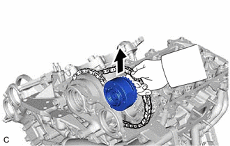
28. DISCONNECT CHAIN SUB-ASSEMBLY (for Bank 1)
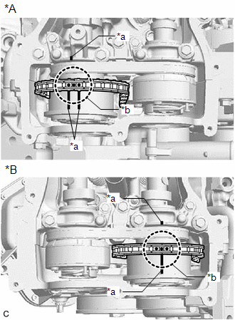
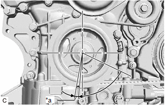
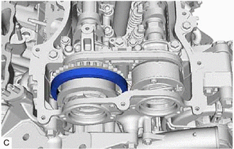
| (a) Turn the crankshaft clockwise until it is in the position shown in the illustration so that there is some slack in the chain sub-assembly between the banks. CAUTION: As the camshafts may turn suddenly, do not touch the camshafts or camshaft timing gears. HINT: When turning the crankshaft, engine oil may spray out of the oil holes. |
|
| (b) Turn the crankshaft clockwise until it is in the position shown in the illustration so that the chain sub-assembly can be removed easily. HINT: When turning the crankshaft, engine oil may spray out of the oil holes. |
|
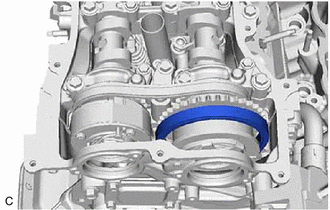
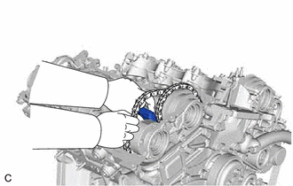
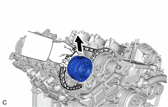
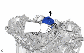
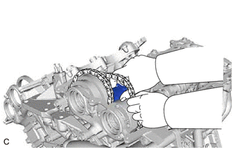
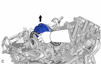
| (c) Remove the chain sub-assembly from the sprocket of the camshaft timing gear assembly and set it on the camshaft timing gear assembly. CAUTION: As the camshaft may turn suddenly and pinch your fingers when the chain sub-assembly is removed, pinch the chain sub-assembly and lift it upward to remove it from the sprocket. |
|
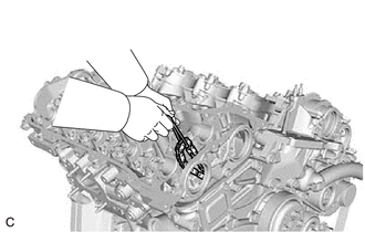
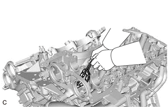
29. SEPARATE NO. 2 CHAIN TENSIONER ASSEMBLY
| (a) Remove the bolt to separate the No. 2 chain tensioner assembly from the camshaft housing sub-assembly. |
|
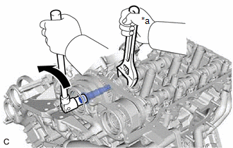
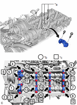
30. REMOVE CAMSHAFT TIMING GEAR BOLT (for Intake Side of Bank 1)
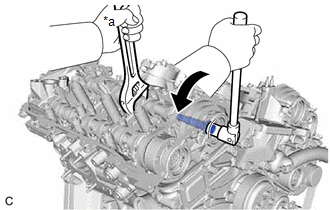
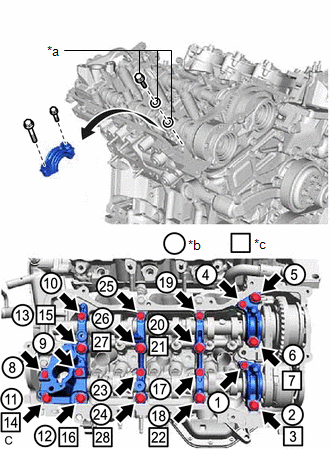
(a) Use a wrench to hold the hexagonal portion of the camshaft and remove the camshaft timing gear bolt from the camshaft timing gear assembly.
|
*a | Hold |
.png) |
Turn |
NOTICE:
- Be careful not to damage the camshaft, camshaft housing sub-assembly or spark plug tube with the wrench.
- If the camshaft timing gear bolt has been struck or dropped, replace it.
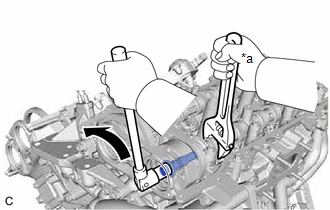
31. REMOVE CAMSHAFT TIMING GEAR BOLT (for Exhaust Side of Bank 1)
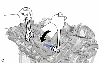
(a) Use a wrench to hold the hexagonal portion of the No. 2 camshaft and remove the camshaft timing gear bolt from the camshaft timing exhaust gear assembly.
NOTICE:
- Be careful not to damage the No. 2 camshaft, camshaft housing sub-assembly or spark plug tube with the wrench.
- If the camshaft timing gear bolt has been struck or dropped, replace it.
|
*a | Hold |
|
|
Turn |
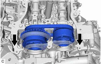
32. REMOVE CAMSHAFT BEARING CAP (for Bank 1)
| (a) Slide the camshaft timing gear assembly and camshaft timing exhaust gear assembly as shown in the illustration. |
|
| (b) Remove the bolts and camshaft bearing caps in the order shown in the illustration. Immediately after removing a camshaft bearing cap, install replacement bolts and washers in the order shown in the illustration. Torque: 10 N·m {102 kgf·cm, 7 ft·lbf} NOTICE:
HINT:
|
|
33. REMOVE NO. 2 CAMSHAFT
| (a) While lifting up the camshaft timing exhaust gear assembly, remove the No. 2 chain tensioner assembly. |
|
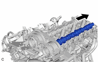
(b) Lift up the rear of the No. 2 camshaft so that it is at an angle.
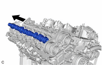
| (c) Pull the No. 2 camshaft as shown in the illustration to remove it from the camshaft timing exhaust gear assembly. |
|
34. REMOVE CAMSHAFT
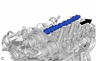
(a) Lift up the rear of the camshaft so that it is at an angle.
| (b) Pull the camshaft as shown in the illustration to remove it from the camshaft timing gear assembly. |
|
35. REMOVE CAMSHAFT TIMING EXHAUST GEAR ASSEMBLY (for Bank 1)
| (a) Remove the camshaft timing exhaust gear assembly. |
|
36. REMOVE CAMSHAFT TIMING GEAR ASSEMBLY (for Bank 1)
| (a) Remove the camshaft timing gear assembly and No. 2 chain sub-assembly. NOTICE: Do not drop the chain sub-assembly into the gap between the engine and timing chain cover assembly. |
|
| (b) Suspend the chain sub-assembly with a string or equivalent. |
|
37. DISCONNECT CHAIN SUB-ASSEMBLY (for Bank 2)
| (a) Turn the crankshaft counterclockwise to align the timing mark (cutout) on the crankshaft pulley with the "0" timing mark on the timing chain cover assembly. |
|
| (b) Remove the chain sub-assembly from the sprocket of the camshaft timing gear assembly and set it on the camshaft timing gear assembly. CAUTION: As the camshaft may turn suddenly and pinch your fingers when the chain sub-assembly is removed, pinch the chain sub-assembly and lift it upward to remove it from the sprocket. |
|
38. SEPARATE NO. 3 CHAIN TENSIONER ASSEMBLY
| (a) Remove the bolt to separate the No. 3 chain tensioner assembly from the camshaft housing sub-assembly LH. |
|
39. REMOVE CAMSHAFT TIMING GEAR BOLT (for Intake Side of Bank 2)
(a) Use a wrench to hold the hexagonal portion of the No. 3 camshaft sub-assembly and remove the camshaft timing gear bolt from the camshaft timing gear assembly.
|
*a | Hold |
|
|
Turn |
NOTICE:
- Be careful not to damage the No. 3 camshaft sub-assembly, camshaft housing sub-assembly LH or spark plug tube with the wrench.
- If the camshaft timing gear bolt has been struck or dropped, replace it.
40. REMOVE CAMSHAFT TIMING GEAR BOLT (for Exhaust Side of Bank 2)
(a) Use a wrench to hold the hexagonal portion of the No. 4 camshaft sub-assembly and remove the camshaft timing gear bolt from the camshaft timing exhaust gear assembly.
|
*a | Hold |
|
|
Turn |
NOTICE:
- Be careful not to damage the No. 4 camshaft sub-assembly, camshaft housing sub-assembly LH or spark plug tube with the wrench.
- If the camshaft timing gear bolt has been struck or dropped, replace it.
41. REMOVE CAMSHAFT BEARING CAP (for Bank 2)
| (a) Slide the camshaft timing gear assembly and camshaft timing exhaust gear assembly as shown in the illustration. |
|
| (b) Remove the bolts and camshaft bearing caps in the order shown in the illustration. Immediately after removing a camshaft bearing cap, install replacement bolts and washers in the order shown in the illustration. Torque: 10 N·m {102 kgf·cm, 7 ft·lbf} NOTICE:
HINT:
|
|
42. REMOVE NO. 4 CAMSHAFT SUB-ASSEMBLY
| (a) While lifting up the camshaft timing exhaust gear assembly, remove the No. 3 chain tensioner assembly. |
|
(b) Lift up the rear of the No. 4 camshaft sub-assembly so that it is at an angle.
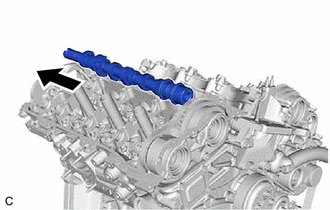
| (c) Pull the No. 4 camshaft sub-assembly as shown in the illustration to remove it from the camshaft timing exhaust gear assembly. |
|
43. REMOVE NO. 3 CAMSHAFT SUB-ASSEMBLY
(a) Lift up the rear of the No. 3 camshaft sub-assembly so that it is at an angle.
| (b) Pull the No. 3 camshaft sub-assembly as shown in the illustration to remove it from the camshaft timing gear assembly. |
|
44. REMOVE CAMSHAFT TIMING EXHAUST GEAR ASSEMBLY (for Bank 2)
| (a) Remove the camshaft timing exhaust gear assembly. |
|
45. REMOVE CAMSHAFT TIMING GEAR ASSEMBLY (for Bank 2)
| (a) Remove the camshaft timing gear assembly and No. 2 chain sub-assembly. NOTICE: Do not drop the chain sub-assembly into the gap between the engine and timing chain cover assembly. |
|
| (b) Suspend the chain sub-assembly with a string or equivalent. |
|
READ NEXT:
 Installation
INSTALLATION PROCEDURE 1. SET NO. 1 CYLINDER TO TDC (COMPRESSION)
(a) Confirm that the timing mark (cutout) on the crankshaft pulley is aligned with the "0" timing mark of the timing chain cover
Precaution
PRECAUTION
HINT:
Any digits beyond the 1/100 mm (1/1000 in.) place for standard, minimum and maximum values should be used as a reference only.
When both standard and maximum or minimum val
SEE MORE:
Message Not Displayed on Multi-information Display When AUTO Function Set to ON/OFF
DESCRIPTION When the AUTO function is set to ON/OFF, a message is displayed on the multi-information display in the combination meter assembly. WIRING DIAGRAM
PROCEDURE
1.
CHECK OPERATION OF AUTO FUNCTION (a) Check that the AUTO function operates when the operating conditions are me
VSC does not Operate or VSC does not Operate Correctly
DESCRIPTION When TRAC or VSC is operating, the skid control ECU (brake actuator assembly) blinks the slip indicator light to inform the driver that slippage occurred.
When a communication malfunction with the ECM is detected, TRAC and VSC are disabled. Also, TRAC and VSC are disabled when a DTC is
