Toyota Camry (XV70): Removal
REMOVAL
CAUTION / NOTICE / HINT
The necessary procedures (adjustment, calibration, initialization, or registration) that must be performed after parts are removed and installed, or replaced during rear crankshaft oil seal removal/installation are shown below.
Necessary Procedure After Parts Removed/Installed/Replaced|
Replaced Part or Performed Procedure |
Necessary Procedure | Effect/Inoperative Function when Necessary Procedure not Performed |
Link |
|---|---|---|---|
| *1: When the ECM is replaced with a new one, reset memory is unnecessary. | |||
| Battery terminal is disconnected/reconnected |
Perform steering sensor zero point calibration |
Lane Tracing Assist System |
|
|
Pre-collision System | |||
|
Memorize steering angle neutral point |
Parking Assist Monitor System |
| |
|
Panoramic view monitor system |
| ||
|
Replacement of ECM | Vehicle Identification Number (VIN) registration |
MIL comes on |
|
|
ECU communication ID registration (Immobiliser system) |
Engine start function |
| |
|
Gas leak from exhaust system is repaired |
Inspection After Repair |
|
|
|
Replacement of automatic transaxle assembly |
|
|
|
|
Replacement of ECM (If possible, read the transaxle compensation code from the previous ECM) |
| ||
| Replacement of ECM (If impossible, read the transaxle compensation code from the previous ECM) |
| ||
| Replacement of ECM |
Code registration |
|
|
|
Replacement of automatic transaxle fluid |
ATF thermal degradation estimate reset |
The value of the Data List item "ATF Thermal Degradation Estimate" is not estimated correctly. |
|
|
Suspension, tires, etc. (The vehicle height changes because of suspension or tire replacement) |
Rear television camera assembly optical axis (Back camera position setting) |
Parking assist monitor system |
|
|
Replacement of front bumper assembly |
Front television camera view adjustment |
Panoramic view monitor system |
|
|
Suspension, tires, etc. (The vehicle height changes because of suspension or tire replacement) |
| ||
| Front wheel alignment adjustment |
|
|
|
PROCEDURE
1. REMOVE AUTOMATIC TRANSAXLE ASSEMBLY
Click here
.gif)
2. REMOVE DRIVE PLATE AND RING GEAR SUB-ASSEMBLY
(a) Using height adjustment attachments and plate lift attachments, place the engine assembly on a flat level surface.
NOTICE:
- Using height adjustment attachments and plate lift attachments, keep the engine assembly level.
- To prevent the No. 2 oil pan sub-assembly from deforming, do not place any attachments under the No. 2 oil pan sub-assembly of the engine assembly.
- Using an engine sling device and engine lift, secure the engine assembly before servicing.
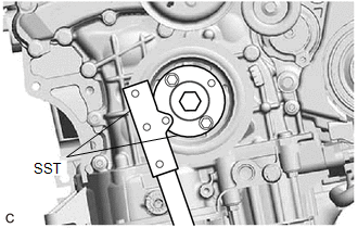
| (b) Using SST, hold the crankshaft pulley. SST: 09213-70011 09213-70020 SST: 09330-00021 |
|
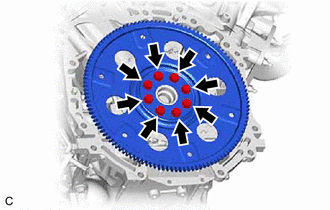
| (c) Remove the 8 bolts, the rear drive plate spacer, the drive plate and ring gear sub-assembly. |
|
3. REMOVE NO. 1 CRANKSHAFT POSITION SENSOR PLATE
(a) Remove the No. 1 crankshaft position sensor plate.
4. REMOVE REAR ENGINE OIL SEAL
| (a) Using a knife, cut through the lip of the rear engine oil seal. |
|
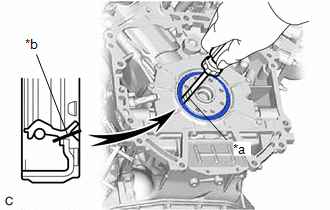
(b) Using a screwdriver with its tip wrapped with protective tape, pry out the rear engine oil seal.
NOTICE:
Be careful not to damage the crankshaft.
READ NEXT:
 Installation
INSTALLATION PROCEDURE 1. INSTALL REAR ENGINE OIL SEAL
(a) Using height adjustment attachments and plate lift attachments, place the engine assembly on a flat level surface.
NOTICE:
Using heig
Fuel Filter
ComponentsCOMPONENTS ILLUSTRATION
*1 FUEL PUMP
*2 FUEL SUCTION PLATE SUB-ASSEMBLY
*3 FUEL SENDER GAUGE ASSEMBLY
*4 FUEL FILTER
*5 FUEL MAIN VALVE ASSEMB
SEE MORE:
Inspection
INSPECTION PROCEDURE 1. INSPECT FRONT DRIVE SHAFT ASSEMBLY
(a) Check that there is no excessive play in the radial direction of the outboard joint.
(b) Check that the inboard joint slides smoothly in the thrust direction.
(c) Check that there is no excessive play in the
Tire pressure warning system
Your vehicle is equipped with a tire pressure warning system that uses
tire pressure warning valve and transmitters to detect low tire inflation
pressure before serious problems arise.
Vehicles without a tire inflation pressure display function
If the tire pressure drops below a predetermined le
