Toyota Camry (XV70): Removal
REMOVAL
CAUTION / NOTICE / HINT
The necessary procedures (adjustment, calibration, initialization or registration) that must be performed after parts are removed and installed, or replaced during fuel main valve assembly removal/installation are shown below.
Necessary Procedures After Parts Removed/Installed/Replaced|
Replaced Part or Performed Procedure |
Necessary Procedure | Effect/Inoperative Function when Necessary Procedure not Performed |
Link |
|---|---|---|---|
|
Battery terminal is disconnected/reconnected |
Perform steering sensor zero point calibration |
Lane Tracing Assist System |
|
|
Pre-collision System | |||
|
Memorize steering angle neutral point |
Parking Assist Monitor System |
| |
|
Panoramic View Monitor System |
| ||
|
Replacement of fuel pump |
Inspection after repair |
|
|
CAUTION:
- Never perform work on fuel system components near any possible ignition sources.
.png)
- Vaporized fuel could ignite, resulting in a serious accident.
- Do not perform work on fuel system components without first disconnecting the cable from the negative (-) battery terminal.
.png)
- Sparks could cause vaporized fuel to ignite, resulting in a serious accident.
PROCEDURE
1. REMOVE FUEL SUCTION TUBE WITH PUMP AND GAUGE ASSEMBLY
Click here .gif)
2. REMOVE FUEL SENDER GAUGE ASSEMBLY
Click here
3. REMOVE FUEL PUMP
Click here
4. REMOVE FUEL MAIN VALVE ASSEMBLY
(a) Remove the fuel main valve assembly (for Low Pressure).
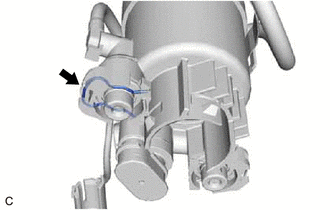
(1) Remove the clip from the fuel filter.
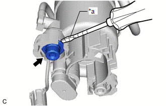
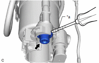
| (2) Using a screwdriver with its tip wrapped with protective tape, remove the fuel main valve assembly from the fuel filter. NOTICE:
|
|
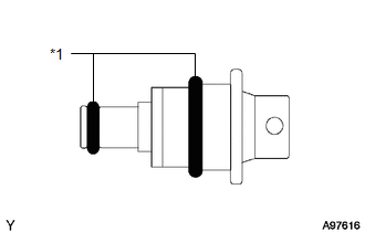
| (3) Remove the 2 O-rings from the fuel main valve assembly. |
|
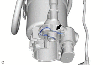
(b) Remove the fuel main valve assembly (for High Pressure).
(1) Remove the clip from the fuel filter.
| (2) Using a screwdriver with its tip wrapped with protective tape, remove the fuel main valve assembly from the fuel filter. NOTICE:
|
|
| (3) Remove the 2 O-rings from the fuel main valve assembly. |
|
READ NEXT:
 Installation
INSTALLATION PROCEDURE 1. INSTALL FUEL MAIN VALVE ASSEMBLY
(a) Apply gasoline to 2 new O-rings. Then install the O-rings to the fuel main valve assembly (for Low Pressure).
(b) Apply gasoline to 2
Components
COMPONENTS ILLUSTRATION
*1 FUEL PRESSURE SENSOR (FUEL DELIVERY PIPE WITH SENSOR ASSEMBLY)
- -
SEE MORE:
Removal
REMOVAL CAUTION / NOTICE / HINT
The necessary procedures (adjustment, calibration, initialization, or registration) that must be performed after parts are removed and installed, or replaced during rear axle carrier sub-assembly removal/installation are shown below. Necessary Procedures After Parts
Right Front Wheel Speed Sensor Circuit Voltage Out of Range (C05061C)
DESCRIPTION Refer to DTC C050612 Click here
DTC No. Detection Item
DTC Detection Condition Trouble Area
C05061C Right Front Wheel Speed Sensor Circuit Voltage Out of Range
When the vehicle is being driven in a straight line at a speed of 20 km/h (12 mph) or mo
