Toyota Camry (XV70): Removal
REMOVAL
CAUTION / NOTICE / HINT
The necessary procedures (adjustment, calibration, initialization, or registration) that must be performed after parts are removed and installed, or replaced during rear axle carrier sub-assembly removal/installation are shown below.
Necessary Procedures After Parts Removed/Installed/Replaced|
Replaced Part or Performed Procedure |
Necessary Procedure | Effect/Inoperative Function when Necessary Procedure not Performed |
Link |
|---|---|---|---|
| Rear wheel alignment adjustment |
|
|
|
|
Suspension, tires, etc. (The vehicle height changes because of suspension or tire replacement) |
Rear television camera assembly optical axis (Back camera position setting) |
Parking assist monitor system |
|
| Panoramic view monitor system |
|
HINT:
- Use the same procedure for the RH side and LH side.
- The following procedure is for the LH side.
PROCEDURE
1. REMOVE REAR WHEEL
Click here
.gif)
2. REMOVE NO. 2 FLOOR UNDER COVER (for LH Side)
Click here
3. REMOVE NO. 1 FLOOR UNDER COVER (for RH Side)
Click here
4. SEPARATE REAR DISC BRAKE CALIPER ASSEMBLY
Click here
5. REMOVE PARKING BRAKE SHOE ADJUSTING HOLE PLUG
Click here
6. REMOVE REAR DISC
Click here
7. DISCONNECT SKID CONTROL SENSOR WIRE
Click here
8. REMOVE REAR AXLE HUB AND BEARING ASSEMBLY
Click here
9. SEPARATE NO. 3 PARKING BRAKE CABLE ASSEMBLY
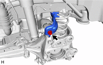
| (a) Remove the nut and separate the No. 3 parking brake cable assembly from the rear trailing arm assembly. |
|
10. SEPARATE PARKING BRAKE ASSEMBLY
| (a) Remove the nut and separate the parking brake assembly from the rear axle carrier sub-assembly. NOTICE: Use wire or an equivalent tool to keep the parking brake assembly from hanging by the No. 3 parking brake cable assembly. |
|
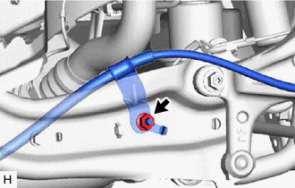
11. REMOVE REAR FLEXIBLE HOSE BRACKET
| (a) Remove the bolt and rear flexible hose bracket from the rear axle carrier sub-assembly. |
|
12. REMOVE REAR STABILIZER LINK ASSEMBLY
Click here
13. REMOVE REAR COIL SPRING
Click here
14. REMOVE REAR LOWER COIL SPRING INSULATOR
Click here
15. REMOVE REAR NO. 1 SUSPENSION ARM ASSEMBLY
Click here
16. REMOVE REAR AXLE CARRIER SUB-ASSEMBLY
| (a) Loosen the 2 bolts of the rear trailing arm assembly. |
|
.png)
| (b) Loosen the nut of the rear shock absorber assembly. NOTICE: Hold the rear axle carrier pin while rotating the nut. |
|
.png)
| (c) Using a jack and a wooden block, support the rear axle carrier sub-assembly. NOTICE:
|
|
.png)
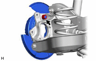
| (d) Loosen the bolt (A). NOTICE: Because the nut has its own stopper, do not turn the nut. Loosen the bolt with the nut secured. |
|
.png)
(e) Remove the 2 bolts and separate the rear trailing arm assembly from the rear axle carrier sub-assembly.
(f) Remove the nut and plate washer, and separate the rear shock absorber assembly from the rear axle carrier sub-assembly.
NOTICE:
Hold the rear axle carrier pin while rotating the nut.
(g) Remove the bolt (A), nut and rear axle carrier sub-assembly from the rear upper control arm assembly.
NOTICE:
Because the nut has its own stopper, do not turn the nut. Loosen the bolt with the nut secured.
READ NEXT:
 Installation
INSTALLATION CAUTION / NOTICE / HINT
HINT:
Use the same procedure for the RH side and LH side.
The following procedure is for the LH side.
PROCEDURE 1. TEMPORARILY INSTALL REAR AXLE CARR
Components
COMPONENTS ILLUSTRATION
*1 NO. 2 PARKING BRAKE WIRE ASSEMBLY
*2 REAR AXLE HUB AND BEARING ASSEMBLY
*3 REAR AXLE SHAFT NUT
*4 REAR DISC
*5 REAR DISC BRAK
SEE MORE:
Disassembly
DISASSEMBLY CAUTION / NOTICE / HINT
CAUTION: If the rear disc brake cylinder assembly has been disassembled, perform air bleeding for the rear disc brake cylinder assembly.
Click here
NOTICE:
Make sure not to scratch, damage or apply excessive force to any of the internal components of t
Terminals Of Ecu
TERMINALS OF ECU HINT: Check from the rear of the connector while it is connected to the components.
RADIO AND DISPLAY RECEIVER ASSEMBLY
Terminal No. (Symbol) Wiring Color
Terminal Description Condition
Specified Condition
K4-1 (FR+) - K3-1 (GND1)
W - BR Soun
