Toyota Camry (XV70): Disassembly
DISASSEMBLY
CAUTION / NOTICE / HINT
CAUTION:
If the rear disc brake cylinder assembly has been disassembled, perform air bleeding for the rear disc brake cylinder assembly.
Click here .gif)
NOTICE:
- Make sure not to scratch, damage or apply excessive force to any of the internal components of the rear disc brake cylinder.
- To prevent rusting on the inside of the rear disc brake cylinder, perform the rear disc brake piston removal and installation quickly.
- Do not clean the interior of the rear disc brake cylinder with brake cleaner.
- Do not remove any parts unless specifically instructed to do so, and only remove the parts indicated.
- Make sure to enter pad replacement mode before removing the rear disc brake cylinder assembly.
Click here
PROCEDURE
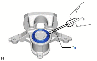
1. REMOVE CYLINDER BOOT
| (a) Using a screwdriver with its tip wrapped with protective tape, remove the cylinder boot from the rear disc brake cylinder. NOTICE: Do not damage the inner surface or cylinder boot groove of the rear disc brake cylinder. |
|
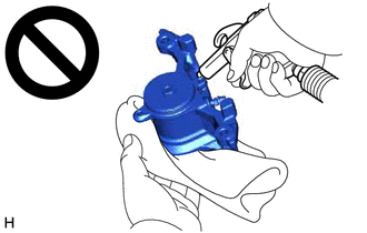
2. REMOVE REAR DISC BRAKE PISTON
| (a) Place a piece of cloth between the rear disc brake piston and rear disc brake cylinder. |
|
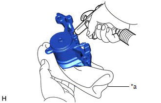
| (b) Apply compressed air to remove the rear disc brake piston from the rear disc brake cylinder. CAUTION:
NOTICE: Do not allow any brake fluid to spatter. |
|
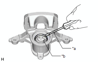
3. REMOVE PISTON SEAL
|
(a) Using a screwdriver with its tip wrapped with protective tape, remove the piston seal from the rear disc brake cylinder. NOTICE:
|
|
4. REMOVE REAR DISC BRAKE BLEEDER PLUG CAP
(a) Remove the rear disc brake bleeder plug cap from the rear disc brake bleeder plug.
5. REMOVE REAR DISC BRAKE BLEEDER PLUG
(a) Remove the rear disc brake bleeder plug from the rear disc brake cylinder.
READ NEXT:
 Inspection
INSPECTION PROCEDURE 1. INSPECT BRAKE CYLINDER AND PISTON
(a) Check the rear disc brake cylinder bore and rear disc brake piston for rust and scoring. If necessary, replace the rear disc brake cylin
Reassembly
REASSEMBLY CAUTION / NOTICE / HINT
CAUTION: If the rear disc brake cylinder assembly has been disassembled, perform air bleeding for the rear disc brake cylinder assembly.
Click here
NOTICE:
Installation
INSTALLATION CAUTION / NOTICE / HINT
NOTICE:
Immediately after installing the brake pads, the braking performance may be reduced. Always perform a road test in a safe place while paying attentio
SEE MORE:
Removal
REMOVAL PROCEDURE 1. REMOVE FRONT WHEEL RH
Click here 2. REMOVE FRONT FENDER APRON SEAL RH
Click here
3. REMOVE V-BANK COVER SUB-ASSEMBLY Click here
4. REMOVE CAMSHAFT TIMING OIL CONTROL SOLENOID ASSEMBLY (for Intake Side of Bank 1)
Click here 5. SET NO. 1 CYLINDER
Components
COMPONENTS ILLUSTRATION
*A for Fold Down Seat Type
- -
*1 REAR SEAT CUSHION ASSEMBLY
*2 REAR SEAT CUSHION LOCK HOOK
*3 REAR SIDE SEATBACK ASSEMBLY LH
*4 REAR SIDE SEATBACK ASSEMBLY RH
*5 REAR CENTER SEAT OUTER BELT ASSEMBLY
*6
