Toyota Camry (XV70): Removal
REMOVAL
PROCEDURE
1. REMOVE FRONT WHEEL RH
Click here .gif)
2. REMOVE FRONT FENDER APRON SEAL RH
Click here
3. REMOVE V-BANK COVER SUB-ASSEMBLY
Click here
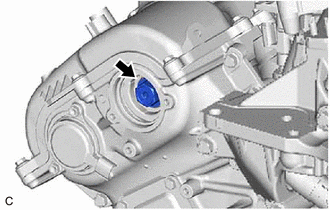
4. REMOVE CAMSHAFT TIMING OIL CONTROL SOLENOID ASSEMBLY (for Intake Side of Bank 1)
Click here
5. SET NO. 1 CYLINDER TO TDC/COMPRESSION
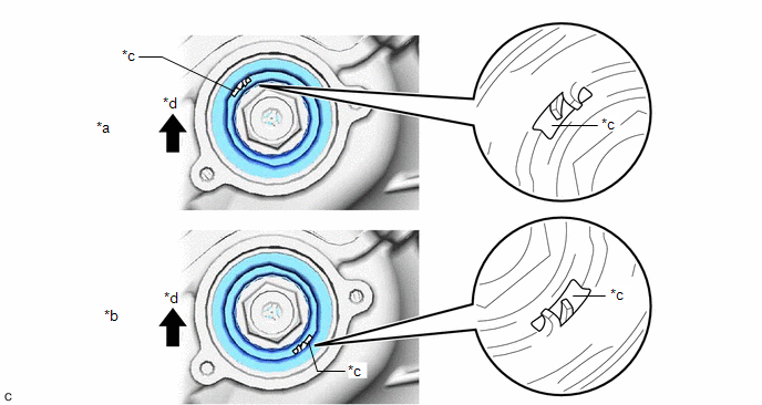
| (a) Turn the crankshaft pulley clockwise until its timing mark (cutout) is aligned with the timing mark on the timing chain cover assembly as shown in the illustration. |
|
.png)
(b) Check that the cutout of the camshaft timing gear assembly is at the top.
|
*a | Correct |
*b | Incorrect |
|
*c | Cutout |
*d | Up |
HINT:
If the cutout of the camshaft timing gear assembly is not at the top, turn the crankshaft 360° clockwise and align the timing mark (cutout) of the crankshaft pulley with the timing mark on the timing chain cover assembly again.
6. REMOVE CAMSHAFT TIMING GEAR BOLT
| (a) While holding the crankshaft pulley, remove the camshaft timing gear bolt. NOTICE:
|
|
READ NEXT:
 Inspection
INSPECTION PROCEDURE 1. INSPECT CAMSHAFT TIMING GEAR BOLT
(a) Check the stroke of the plunger in the center of the camshaft timing gear bolt.
Standard Stroke: 4.5 mm (0.177 in.) or more HINT
Installation
INSTALLATION PROCEDURE 1. INSTALL CAMSHAFT TIMING GEAR BOLT
(a) Make sure that the No. 1 cylinder is at TDC/compression. HINT:
Check that the cutout of the camshaft timing gear assembly is at the
SEE MORE:
On-vehicle Inspection
ON-VEHICLE INSPECTION PROCEDURE
1. REMOVE COWL TOP VENTILATOR LOUVER SUB-ASSEMBLY Click here
2. REMOVE FRONT CENTER UPPER SUSPENSION BRACE SUB-ASSEMBLY
Click here
3. OPERATION CHECK (a) Slide the clip and disconnect the air tube from the vacuum pump assembly.
(b) Connect the hose
Throttle/Pedal Position Sensor/Switch "A"/"B" Voltage Correlation Signal Cross Coupled (P21352B)
DESCRIPTION Refer to DTC P012011. Click here
DTC No. Detection Item
DTC Detection Condition Trouble Area
MIL Memory
Note P21352B
Throttle/Pedal Position Sensor/Switch "A"/"B" Voltage Correlation Signal Cross Coupled
The difference between the output vol
