Toyota Camry (XV70): Right Rear Wheel Speed Sensor Circuit Short to Battery (C051212)
DESCRIPTION
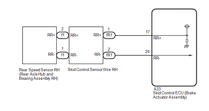
Each speed sensor detects wheel speed and sends signals to the skid control ECU (brake actuator assembly). These signals are used by the ABS control.
The speed sensor detects the magnetic fields of the speed sensor rotor as it rotates and outputs a pulse signal.
The frequency of the pulse varies in accordance with the rotational speed of the speed sensor rotor and the system uses this to determine the wheel speed.
|
DTC No. | Detection Item |
DTC Detection Condition | Trouble Area |
|---|---|---|---|
|
C051212 | Right Rear Wheel Speed Sensor Circuit Short to Battery |
A short to +B in the speed sensor signal circuit is detected for 0.12 seconds or more. |
|
WIRING DIAGRAM
CAUTION / NOTICE / HINT
NOTICE:
- After replacing the skid control ECU (brake actuator assembly), perform acceleration sensor zero point calibration and system information memorization.
Click here
.gif)
- After replacing or removing and installing a speed sensor, perform Dealer Mode (Signal Check) inspection to confirm that the speed sensors are operating correctly.
Click here
PROCEDURE
|
1. | CHECK HARNESS AND CONNECTOR (SENSOR GROUND CIRCUIT) |
| (a) Make sure that there is no looseness at the locking part and the connecting part of the connectors. OK: The connector is securely connected. |
|
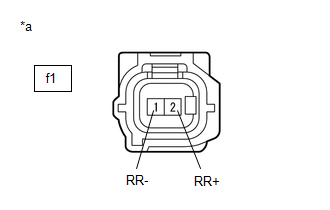
(b) Disconnect the f1 rear speed sensor RH (rear axle hub and bearing assembly RH) connector.
(c) Check both the connector case and the terminals for deformation and corrosion.
OK:
No deformation or corrosion.
(d) Turn the ignition switch to ON.
(e) Measure the voltage according to the value(s) in the table below.
Standard Voltage:
|
Tester Connection | Condition |
Specified Condition |
|---|---|---|
|
f1-2 (RR+) - f1-1 (RR-) |
Ignition switch ON | 11 to 14 V |
| OK | .gif) | REPLACE REAR AXLE HUB AND BEARING ASSEMBLY RH |
|
.gif)
| 2. |
CHECK HARNESS AND CONNECTOR (SENSOR GROUND CIRCUIT) |
| (a) Make sure that there is no looseness at the locking part and the connecting part of the connectors. OK: The connector is securely connected. |
|
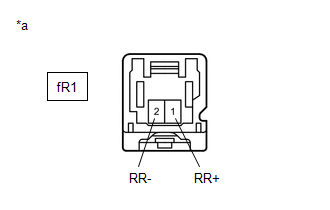
(b) Disconnect the fR1 skid control sensor wire RH connector.
(c) Check both the connector case and the terminals for deformation and corrosion.
OK:
No deformation or corrosion.
(d) Turn the ignition switch to ON.
(e) Measure the voltage according to the value(s) in the table below.
Standard Voltage:
|
Tester Connection | Condition |
Specified Condition |
|---|---|---|
|
fR1-1 (RR+) - fR1-2 (RR-) |
Ignition switch ON | 11 to 14 V |
| OK | | REPLACE SKID CONTROL SENSOR WIRE RH |
|
| 3. |
CHECK HARNESS AND CONNECTOR (SKID CONTROL SENSOR WIRE RH - BRAKE ACTUATOR ASSEMBLY) |
| (a) Make sure that there is no looseness at the locking part and the connecting part of the connectors. OK: The connector is securely connected. |
|
(b) Disconnect the A33 skid control ECU (brake actuator assembly) connector.
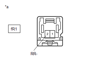
(c) Disconnect the fR1 skid control sensor wire RH connector.
(d) Check both the connector case and the terminals for deformation and corrosion.
OK:
No deformation or corrosion.
(e) Measure the voltage according to the value(s) in the table below.
Standard Voltage:
|
Tester Connection | Condition |
Specified Condition |
|---|---|---|
|
fR1-2 (RR-) - Body ground |
Always | Below 1.5 V |
| NG | | REPAIR OR REPLACE HARNESS OR CONNECTOR |
|
| 4. |
CHECK HARNESS AND CONNECTOR (SKID CONTROL SENSOR WIRE RH - BRAKE ACTUATOR ASSEMBLY) |
(a) Make sure that there is no looseness at the locking part and the connecting part of the connectors.
OK:
The connector is securely connected.
(b) Disconnect the A33 skid control ECU (brake actuator assembly) connector.
(c) Disconnect the fR1 skid control sensor wire RH connector.
(d) Check both the connector case and the terminals for deformation and corrosion.
OK:
No deformation or corrosion.
(e) Measure the resistance according to the value(s) in the table below.
Standard Resistance:
|
Tester Connection | Condition |
Specified Condition |
|---|---|---|
|
fR1-1 (RR+) or A33-17 (RR+) - fR1-2 (RR-) or A33-29 (RR-) |
Always | 10 kΩ or higher |
| OK | | REPLACE BRAKE ACTUATOR ASSEMBLY |
| NG | | REPAIR OR REPLACE HARNESS OR CONNECTOR |
READ NEXT:
 Right Rear Wheel Speed Sensor Circuit Short to Ground or Open (C051214)
DESCRIPTION Refer to DTC C051212 Click here
DTC No. Detection Item
DTC Detection Condition Trouble Area
C051214 Right Rear Wheel Speed Sensor Circuit Short to Ground or Op
Right Rear Wheel Speed Sensor Circuit Voltage Out of Range (C05121C)
DESCRIPTION Refer to DTC C051212 Click here
DTC No. Detection Item
DTC Detection Condition Trouble Area
C05121C Right Rear Wheel Speed Sensor Circuit Voltage Out of Range
Right Rear Wheel Speed Sensor Circuit Intermittent (C05121F)
DESCRIPTION Refer to DTC C051212 Click here
DTC No. Detection Item
DTC Detection Condition Trouble Area
C05121F Right Rear Wheel Speed Sensor Circuit Intermittent
SEE MORE:
Vehicle Lift And Support Locations
VEHICLE LIFT AND SUPPORT LOCATIONS NOTICE ABOUT VEHICLE CONDITION WHEN RAISING VEHICLE
(a) The vehicle must be unloaded before jacking up or raising the vehicle. Never jack up or raise a heavily loaded vehicle.
(b) When removing any heavy components like the engine or transmission, the vehicle c
Panoramic moon roof
Use the overhead switches to operate the panoramic moon roof
and electronic sunshade.
Opening and closing the electronic sunshade
Opens the electronic sunshade
Slide and hold the switch
backward. The electronic sunshade
will fully open automatically.*
Closes the electronic sunshade
