Toyota Camry (XV70): Right Rear Wheel Speed Sensor Circuit Short to Ground or Open (C051214)
DESCRIPTION
Refer to DTC C051212
Click here
.gif)
|
DTC No. | Detection Item |
DTC Detection Condition | Trouble Area |
|---|---|---|---|
|
C051214 | Right Rear Wheel Speed Sensor Circuit Short to Ground or Open |
A short or open circuit is detected in the speed sensor signal circuit for 0.12 seconds or more. |
|
*1: for 2WD
*2: for AWD
DTC Detection Conditions: C051214|
Vehicle Condition | |||
|---|---|---|---|
|
Pattern 1 | Pattern 2 | ||
|
Diagnosis Condition | - |
- | - |
|
Malfunction Status | An open circuit is detected in the speed sensor signal circuit. |
○ | - |
|
A short circuit is detected in the speed sensor signal circuit. |
- | ○ | |
|
Detection Time | 0.12 seconds or more. |
0.12 seconds or more. | |
|
Number of Trips | 1 trip |
1 trip | |
HINT:
DTC will be output when conditions for either of the patterns in the table above are met.
WIRING DIAGRAM
Refer to DTC C051212.
Click here
CAUTION / NOTICE / HINT
NOTICE:
- After replacing the skid control ECU (brake actuator assembly), perform acceleration sensor zero point calibration and system information memorization.
Click here
- After replacing or removing and installing a speed sensor, perform Dealer Mode (Signal Check) inspection to confirm that the speed sensors are operating correctly.
Click here
PROCEDURE
|
1. | CHECK VEHICLE |
(a) Check the vehicle specification.
| Result |
Proceed to |
|---|---|
| for 2WD |
A |
| for AWD |
B |
| B |
.gif) | GO TO STEP 7 |
|
.gif)
| 2. |
CHECK HARNESS AND CONNECTOR (SENSOR GROUND CIRCUIT) |
| (a) Make sure that there is no looseness at the locking part and the connecting part of the connectors. OK: The connector is securely connected. |
|
.png)
(b) Disconnect the u2 rear speed sensor RH (rear axle hub and bearing assembly RH) connector.
(c) Check both the connector case and the terminals for deformation and corrosion.
OK:
No deformation or corrosion.
(d) Turn the ignition switch to ON.
(e) Measure the voltage according to the value(s) in the table below.
Standard Voltage:
|
Tester Connection | Condition |
Specified Condition |
|---|---|---|
|
u2-2 (RA+) - u2-1 (RA-) |
Ignition switch on | 11 to 14 V |
| NG | | GO TO STEP 5 |
|
| 3. |
INSPECT NO. 1 PARKING BRAKE WIRE ASSEMBLY |
| (a) Make sure that there is no looseness at the locking part and the connecting part of the connectors. OK: The connector is securely connected. |
|
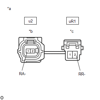
(b) Disconnect the u2 skid control sensor wire RH (No. 1 parking brake wire assembly) connector.
(c) Disconnect the uR1 skid control sensor wire RH (No. 1 parking brake wire assembly) connector.
(d) Check both the connector case and the terminals for deformation and corrosion.
OK:
No deformation or corrosion.
(e) Measure the resistance according to the value(s) in the table below.
Standard Resistance:
|
Tester Connection | Condition |
Specified Condition |
|---|---|---|
|
u2-1 (RA-) or uR1-2 (RR-) - Body ground and other terminals |
Always | 10 kΩ or higher |
| NG | | REPLACE NO. 1 PARKING BRAKE WIRE ASSEMBLY |
|
| 4. |
CHECK HARNESS AND CONNECTOR (NO. 1 PARKING BRAKE WIRE ASSEMBLY - BRAKE ACTUATOR ASSEMBLY) |
(a) Make sure that there is no looseness at the locking part and the connecting part of the connectors.
OK:
The connector is securely connected.
(b) Disconnect the A34 skid control ECU (brake actuator assembly) connector.
(c) Disconnect the uR1 skid control sensor wire RH (No. 1 parking brake wire assembly) connector.
(d) Check both the connector case and the terminals for deformation and corrosion.
OK:
No deformation or corrosion.
(e) Measure the resistance according to the value(s) in the table below.
Standard Resistance:
|
Tester Connection | Condition |
Specified Condition |
|---|---|---|
|
uR1-2 (RR-) or A34-37 (RR-) - Body ground |
Always | 10 kΩ or higher |
| OK | | REPLACE REAR AXLE HUB AND BEARING ASSEMBLY RH |
| NG | | REPAIR OR REPLACE HARNESS OR CONNECTOR |
| 5. |
INSPECT NO. 1 PARKING BRAKE WIRE ASSEMBLY |
| (a) Make sure that there is no looseness at the locking part and the connecting part of the connectors. OK: The connector is securely connected. |
|
(b) Disconnect the u2 skid control sensor wire RH (No. 1 parking brake wire assembly) connector.
(c) Disconnect the uR1 skid control sensor wire RH (No. 1 parking brake wire assembly) connector.
(d) Check both the connector case and the terminals for deformation and corrosion.
OK:
No deformation or corrosion.
(e) Measure the resistance according to the value(s) in the table below.
Standard Resistance:
|
Tester Connection | Condition |
Specified Condition |
|---|---|---|
|
u2-1 (RA-) - uR1-2 (RR-) |
Always | Below 1 Ω |
| NG | | REPLACE NO. 1 PARKING BRAKE WIRE ASSEMBLY |
|
| 6. |
CHECK HARNESS AND CONNECTOR (NO. 1 PARKING BRAKE WIRE ASSEMBLY - BRAKE ACTUATOR ASSEMBLY) |
(a) Make sure that there is no looseness at the locking part and the connecting part of the connectors.
OK:
The connector is securely connected.
(b) Disconnect the A34 skid control ECU (brake actuator assembly) connector.
(c) Disconnect the uR1 skid control sensor wire RH (No. 1 parking brake wire assembly) connector.
(d) Check both the connector case and the terminals for deformation and corrosion.
OK:
No deformation or corrosion.
(e) Measure the resistance according to the value(s) in the table below.
Standard Resistance:
|
Tester Connection | Condition |
Specified Condition |
|---|---|---|
|
uR1-2 (RR-) - A34-37 (RR-) |
Always | Below 1 Ω |
| OK | | REPLACE BRAKE ACTUATOR ASSEMBLY |
| NG | | REPAIR OR REPLACE HARNESS OR CONNECTOR |
| 7. |
CHECK HARNESS AND CONNECTOR (SENSOR GROUND CIRCUIT) |
| (a) Make sure that there is no looseness at the locking part and the connecting part of the connectors. OK: The connector is securely connected. |
|
(b) Disconnect the u2 rear speed sensor RH connector.
(c) Check both the connector case and the terminals for deformation and corrosion.
OK:
No deformation or corrosion.
(d) Turn the ignition switch to ON.
(e) Measure the voltage according to the value(s) in the table below.
Standard Voltage:
|
Tester Connection | Condition |
Specified Condition |
|---|---|---|
|
u2-2 (RA+) - u2-1 (RA-) |
Ignition switch on | 11 to 14 V |
| NG | | GO TO STEP 5 |
|
| 8. |
INSPECT NO. 1 PARKING BRAKE WIRE ASSEMBLY |
| (a) Make sure that there is no looseness at the locking part and the connecting part of the connectors. OK: The connector is securely connected. |
|
(b) Disconnect the u2 skid control sensor wire RH (No. 1 parking brake wire assembly) connector.
(c) Disconnect the uR1 skid control sensor wire RH (No. 1 parking brake wire assembly) connector.
(d) Check both the connector case and the terminals for deformation and corrosion.
OK:
No deformation or corrosion.
(e) Measure the resistance according to the value(s) in the table below.
Standard Resistance:
|
Tester Connection | Condition |
Specified Condition |
|---|---|---|
|
u2-1 (RA-) or uR1-2 (RR-) - Body ground and other terminals |
Always | 10 kΩ or higher |
| NG | | REPLACE NO. 1 PARKING BRAKE WIRE ASSEMBLY |
|
| 9. |
CHECK HARNESS AND CONNECTOR (NO. 1 PARKING BRAKE WIRE ASSEMBLY - BRAKE ACTUATOR ASSEMBLY) |
(a) Make sure that there is no looseness at the locking part and the connecting part of the connectors.
OK:
The connector is securely connected.
(b) Disconnect the A34 skid control ECU (brake actuator assembly) connector.
(c) Disconnect the uR1 skid control sensor wire RH (No. 1 parking brake wire assembly) connector.
(d) Check both the connector case and the terminals for deformation and corrosion.
OK:
No deformation or corrosion.
(e) Measure the resistance according to the value(s) in the table below.
Standard Resistance:
|
Tester Connection | Condition |
Specified Condition |
|---|---|---|
|
uR1-2 (RR-) or A34-37 (RR-) - Body ground |
Always | 10 kΩ or higher |
| OK | | REPLACE REAR SPEED SENSOR RH |
| NG | | REPAIR OR REPLACE HARNESS OR CONNECTOR |
READ NEXT:
 Right Rear Wheel Speed Sensor Circuit Voltage Out of Range (C05121C)
DESCRIPTION Refer to DTC C051212 Click here
DTC No. Detection Item
DTC Detection Condition Trouble Area
C05121C Right Rear Wheel Speed Sensor Circuit Voltage Out of Range
Right Rear Wheel Speed Sensor Circuit Intermittent (C05121F)
DESCRIPTION Refer to DTC C051212 Click here
DTC No. Detection Item
DTC Detection Condition Trouble Area
C05121F Right Rear Wheel Speed Sensor Circuit Intermittent
Right Rear Wheel Speed Sensor Signal Stuck Low (C051223)
DESCRIPTION Refer to DTC C051212 Click here
DTC No. Detection Item
DTC Detection Condition Trouble Area
C051223 Right Rear Wheel Speed Sensor Signal Stuck Low
W
SEE MORE:
Identification Information
Vehicle Identification And Serial NumbersVEHICLE IDENTIFICATION AND SERIAL NUMBERS
VEHICLE IDENTIFICATION NUMBER (a) The vehicle identification number is stamped on the vehicle body and on the certification label or name label as shown in the illustration.
*1 Vehicle Identification Nu
Recommended fluids and lubricants
Fluids and lubricants
*1: For additional information, see “engine oil recommendation”.
*2: As an alternative to this recommended oil, sae 5w-30 conventional
petroleum based oil may be used and meet all specifications
and requirements necessary to maintain the new vehicle limited
